1. Introduction
Thank you for choosing the Yato YT-73084 Digital Multimeter. This manual provides essential information for the safe and effective use of your device. Please read it thoroughly before operation and keep it for future reference. This multimeter is designed for measuring various electrical parameters including DC/AC voltage, DC/AC current, resistance, temperature, diode, continuity, and transistor hFE.
2. Safety Information
WARNING: Electrical shock hazard. Failure to follow these safety instructions can result in serious injury or death.
- Always ensure the multimeter is in good working condition before use. Inspect test leads for damage.
- Do not attempt to measure voltages or currents exceeding the specified maximum limits of the device.
- Never touch the exposed metal parts of the test leads or the circuit being tested.
- Be cautious when working with voltages above 30V AC RMS, 42V peak, or 60V DC, as these pose a shock hazard.
- Always disconnect the test leads from the circuit before changing the function switch.
- Replace batteries promptly when the low battery indicator appears to ensure accurate readings.
- Do not operate the multimeter in explosive atmospheres or in the presence of flammable gases or dust.
- Ensure the correct function and range are selected for the measurement being performed.
3. Product Overview
The Yato YT-73084 is a compact digital multimeter featuring an auto-ranging function for ease of use. It includes a clear LCD display, a rotary switch for function selection, and input jacks for test leads.

Figure 3.1: Front view of the Yato YT-73084 Digital Multimeter, showing the display, function buttons, rotary switch, and input jacks.

Figure 3.2: Close-up of the Yato YT-73084 branding and key measurement capabilities, including voltage, current, resistance, capacitance, and temperature ranges.
3.1 Components
- LCD Display: Shows measurement readings, units, and indicators.
- Function Buttons: Include 'FUNC', 'RANGE', 'MAX/MIN', 'DATA.H' for additional features.
- Rotary Switch: Used to select the desired measurement function (e.g., V~, V-, A~, A-, Ω, Temp, Diode, Continuity, hFE).
- Input Jacks:
- COM: Common jack for the black test lead.
- VΩmA: Input for voltage, resistance, and small current measurements (red test lead).
- 10A: Input for high current measurements up to 10A (red test lead).
4. Setup
4.1 Battery Installation
The multimeter is powered by batteries. To install or replace batteries:
- Ensure the multimeter is turned off and test leads are disconnected.
- Locate the battery compartment on the back of the device.
- Unscrew the retaining screw(s) and remove the battery cover.
- Insert new batteries, observing the correct polarity (+/-).
- Replace the battery cover and secure it with the screw(s).
4.2 Connecting Test Leads
Always connect the black test lead to the 'COM' jack. Connect the red test lead to the appropriate jack based on the measurement type:
- For voltage, resistance, continuity, diode, temperature, and small current measurements (mA): Connect the red lead to the VΩmA jack.
- For high current measurements (up to 10A): Connect the red lead to the 10A jack.
5. Operating Instructions
Before taking any measurement, ensure the test leads are correctly connected and the rotary switch is set to the desired function.
5.1 Measuring DC Voltage (V-)
- Set the rotary switch to the V- position.
- Connect the red test lead to the positive (+) side of the circuit and the black test lead to the negative (-) side.
- Read the voltage value on the LCD display.
5.2 Measuring AC Voltage (V~)
- Set the rotary switch to the V~ position.
- Connect the test leads across the AC voltage source.
- Read the voltage value on the LCD display.

Figure 5.1: The Yato YT-73084 Multimeter in use, measuring voltage from a wall outlet, demonstrating proper probe placement.
5.3 Measuring Current (A-, A~)
CAUTION: To measure current, the multimeter must be connected in series with the circuit. Never connect it in parallel across a voltage source, as this can damage the multimeter and the circuit.
- Determine if the current is DC (A-) or AC (A~).
- Select the appropriate current range on the rotary switch (e.g., mA or 10A).
- If measuring high current (above 200mA), move the red test lead to the 10A jack.
- Break the circuit and connect the multimeter in series.
- Read the current value on the LCD display.
5.4 Measuring Resistance (Ω)
- Ensure the circuit or component is de-energized before measuring resistance.
- Set the rotary switch to the Ω position.
- Connect the test leads across the component to be measured.
- Read the resistance value on the LCD display.
5.5 Diode Test (→|→)
- Set the rotary switch to the Diode position.
- Connect the red test lead to the anode and the black test lead to the cathode of the diode.
- The display will show the forward voltage drop. Reverse the leads; the display should show 'OL' (Open Loop) for a good diode.
5.6 Continuity Test (♫)
- Set the rotary switch to the Continuity position.
- Connect the test leads across the circuit or component.
- If continuity exists (resistance below a certain threshold), the buzzer will sound.
5.7 Temperature Measurement (Temp)
- Set the rotary switch to the Temp position.
- Connect the temperature probe (if included and compatible) to the input jacks, observing polarity.
- Place the probe tip on or near the object whose temperature is to be measured.
- Read the temperature value on the LCD display.
5.8 Transistor hFE Test (hFE)
- Set the rotary switch to the hFE position.
- Insert the transistor leads into the appropriate NPN or PNP sockets on the multimeter's hFE test socket.
- Read the hFE (DC current gain) value on the LCD display.
6. Maintenance
6.1 Cleaning
Wipe the case with a damp cloth and mild detergent. Do not use abrasives or solvents. Ensure the device is dry before use.
6.2 Battery Replacement
When the low battery indicator appears on the display, replace the batteries as described in Section 4.1. Remove batteries if the device will not be used for an extended period to prevent leakage.
6.3 Storage
Store the multimeter in a cool, dry place, away from direct sunlight and extreme temperatures. Keep it out of reach of children.
7. Troubleshooting
- No display or faint display: Check battery installation and charge. Replace batteries if necessary.
- Incorrect readings: Ensure test leads are properly connected to the correct input jacks. Verify the rotary switch is set to the appropriate function and range. Check for damaged test leads.
- 'OL' (Overload) displayed: The measured value exceeds the selected range. Switch to a higher range or ensure the circuit is within the multimeter's capabilities.
- No continuity beep: Ensure the continuity function is selected and the circuit is de-energized. Check if the component has high resistance.
8. Specifications
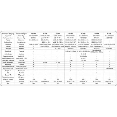
Figure 8.1: Detailed technical specifications for various Yato multimeter models, including the YT-73084.
| Parameter | Value |
|---|---|
| Brand | Yato |
| Model Number | YT-73084 |
| Product Dimensions (L x W x H) | 15.8 x 3.5 x 7.5 cm |
| Weight | 276 grams |
| Power Source | Battery Powered |
| Style | Digital |
| Color | Red/Black |
| Compliant Specifications | CE |
| Upper Temperature Rating | 1000 Degrees Celsius |
| Measurement Type | Multimeter |
| International Article Code | 05906083730849 |
| Temperature Measurement Range | -20°C to 1000°C |
| Resistance Measurement Range | Up to 20 MOhm |
9. Warranty and Support
For warranty information and technical support, please refer to the documentation provided with your purchase or contact your retailer. You may also visit the official Yato website for further assistance.
Yato products are designed for performance and durability. If you encounter any issues not covered in this manual, please seek professional assistance or contact Yato customer service.


