
1. Introduction
This manual provides essential information for the safe and effective installation, operation, and maintenance of the LEFOO Heavy Duty Pressure Switch, model LF10A-1H. This pressure switch is designed for use with air compressors, offering reliable pressure control within a 135-175 psi range and handling up to 26 Amps.
2. Safety Information
WARNING: Electrical shock hazard. Disconnect power before installation or servicing. High pressure air systems can cause serious injury. Ensure all pressure is relieved before working on the system.
- Always ensure the power supply to the compressor is disconnected before attempting any installation, wiring, or maintenance.
- Verify that the pressure in the air system is fully discharged before connecting or disconnecting the pressure switch.
- Installation and wiring should only be performed by qualified personnel in accordance with all local and national electrical codes.
- Do not exceed the specified electrical ratings (26 Amps) or pressure range (135-175 psi).
- Ensure proper grounding of the compressor system.
3. Setup and Installation
The LEFOO LF10A-1H pressure switch is designed for wall mounting and features a single port for pressure connection. Refer to the internal wiring diagram for electrical connections.
3.1 Mounting
Mount the pressure switch securely to a stable surface, such as a wall or compressor frame, using appropriate fasteners. Ensure the mounting location allows for easy access to the manual operation lever and wiring terminals.
3.2 Pressure Connection
Connect the single pressure port of the switch to the air compressor's pressure line. Use appropriate thread sealant to ensure an airtight connection. The port typically accommodates standard pipe fittings.

Figure 1: Bottom view of the LEFOO LF10A-1H pressure switch, highlighting the single pressure port for connection to the air compressor system.
3.3 Electrical Wiring
The pressure switch is rated for 26 Amps and operates as a normally closed, 1-way circuit. The terminals are screw-type. A wiring diagram is typically located inside the switch cover. Ensure all connections are tight and insulated.
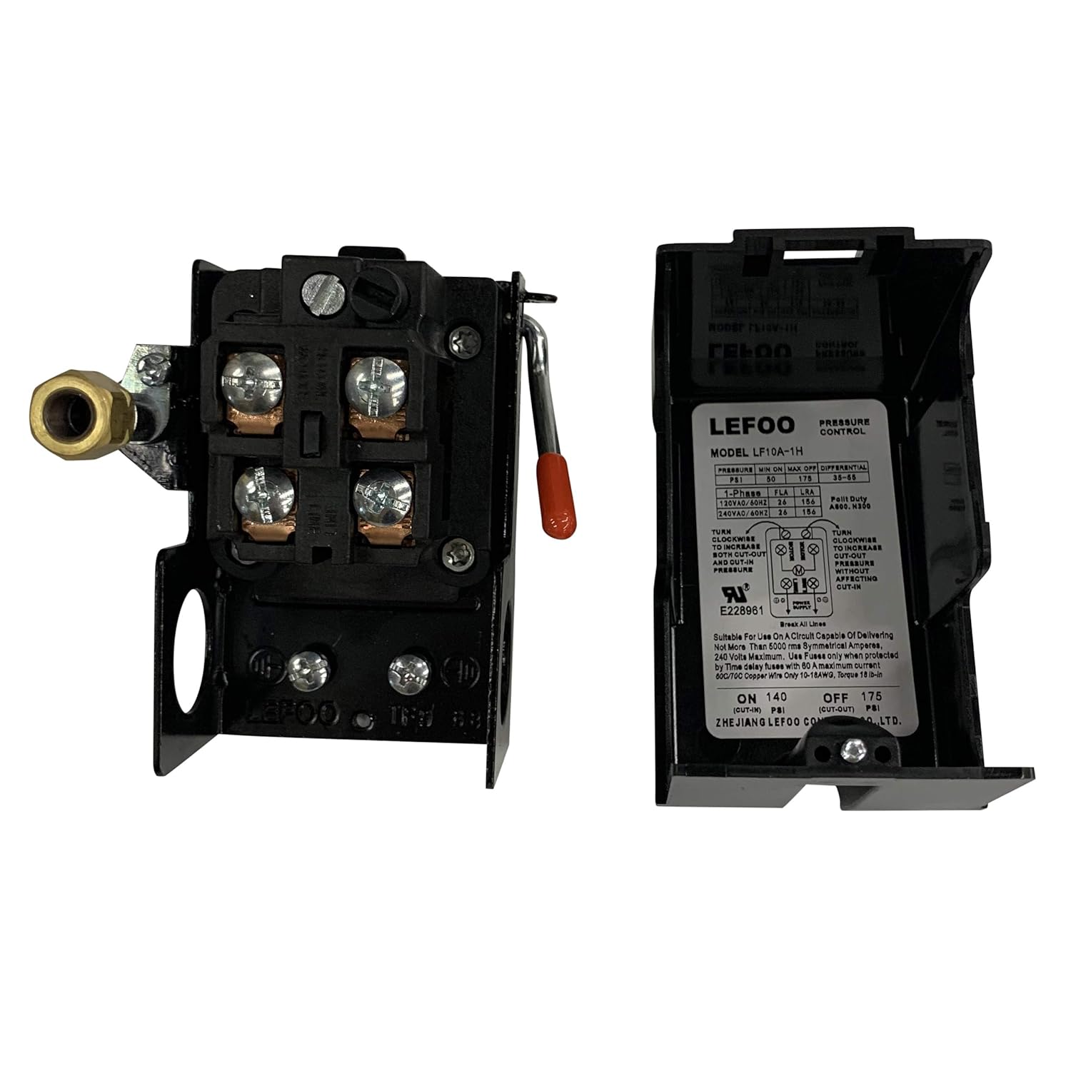
Figure 2: Internal view of the LEFOO LF10A-1H pressure switch, displaying the screw terminals for electrical connections and the integrated wiring diagram on the cover.

Figure 3: Top-down internal view of the LEFOO LF10A-1H pressure switch, illustrating the contact points and internal mechanism.
4. Operating Instructions
The LEFOO LF10A-1H features manual operation and adjustable pressure settings.
4.1 Manual Operation
The switch includes a manual ON/OFF lever. Use this lever to manually start or stop the air compressor. Ensure the lever is in the "ON" position for automatic pressure control.
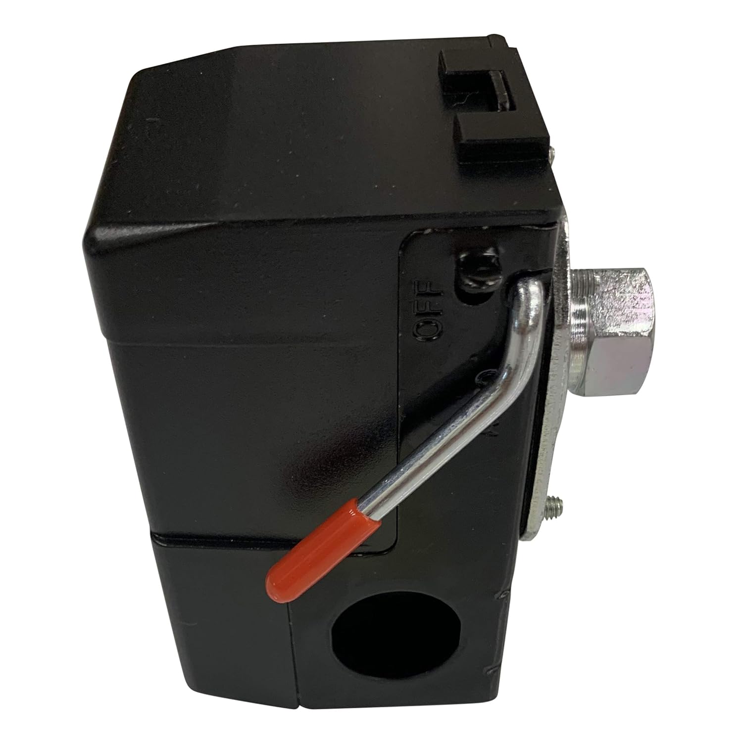
Figure 4: Side view of the LEFOO LF10A-1H pressure switch, showing the red-tipped manual ON/OFF lever.
4.2 Pressure Adjustment
The pressure switch is factory set to operate within a 135-175 psi range. Adjustment screws inside the cover allow for fine-tuning of the cut-in and cut-out pressures. Refer to the internal diagram for specific adjustment points. Always make small adjustments and test the system to achieve desired pressure settings. The minimum differential pressure is typically 35 psi.

Figure 5: Front view of the LEFOO LF10A-1H pressure switch, displaying the LEFOO brand and "PRESSURE CONTROL" text.
5. Maintenance
Regular maintenance ensures optimal performance and longevity of your pressure switch.
- Visual Inspection: Periodically inspect the switch for any signs of damage, corrosion, or loose connections.
- Cleaning: Keep the exterior of the switch clean and free from dust and debris. Do not use harsh chemicals.
- Connection Check: Ensure all electrical and pressure connections remain tight.
- Bleeder Valve: If equipped, ensure the bleeder valve operates correctly and does not leak when the compressor is running.
6. Troubleshooting
This section addresses common issues you might encounter with the pressure switch.
- Compressor does not start:
- Check if the manual ON/OFF lever is in the "ON" position.
- Verify power supply to the compressor and switch.
- Inspect electrical wiring for loose connections or damage.
- Ensure the pressure in the tank is below the cut-in pressure setting.
- Compressor does not stop:
- Check if the pressure in the tank has reached the cut-out pressure setting.
- Inspect the pressure sensing mechanism for blockages or damage.
- Verify internal contacts are not stuck in the closed position.
- Ensure the pressure adjustment screws are correctly set.
- Air leak from switch:
- Check the pressure port connection for proper sealing.
- Inspect the bleeder valve (if present) for proper function and sealing.
- Examine the switch housing for cracks or damage.
- Inconsistent pressure control:
- Re-calibrate the pressure adjustment settings.
- Ensure the pressure sensing line is clear and unobstructed.
- Verify stable power supply.
7. Specifications
| Feature | Specification |
|---|---|
| Model Number | LF10A-1H |
| Brand | LEFOO |
| Pressure Range | 135-175 psi (adjustable) |
| Current Rating | 26 Amps |
| Operation Mode | Manual |
| Contact Type | Normally Closed |
| Connector Type | Single Port |
| Circuit Type | 1-way |
| Terminal Type | Screw |
| Mounting Type | Wall Mount |
| Contact Material | Copper, Brass |
| Package Dimensions | 4.02 x 3.9 x 3.5 inches |
| Weight | 8.01 ounces |
8. Warranty Information
Specific warranty details for the LEFOO LF10A-1H pressure switch are not provided in this document. Please refer to the product packaging or contact LEFOO customer service for current warranty terms and conditions.
9. Customer Support
For technical assistance, troubleshooting beyond this manual, or warranty inquiries, please contact LEFOO customer service. Visit the official LEFOO website for contact information.
Note: Always provide your product model number (LF10A-1H) when contacting support.


