1. Introduction
Thank you for choosing the PORTER-CABLE FR350B Full Round Framing Nailer. This manual provides essential information for the safe and effective operation, maintenance, and troubleshooting of your tool. Please read this manual thoroughly before operating the nailer and keep it for future reference.
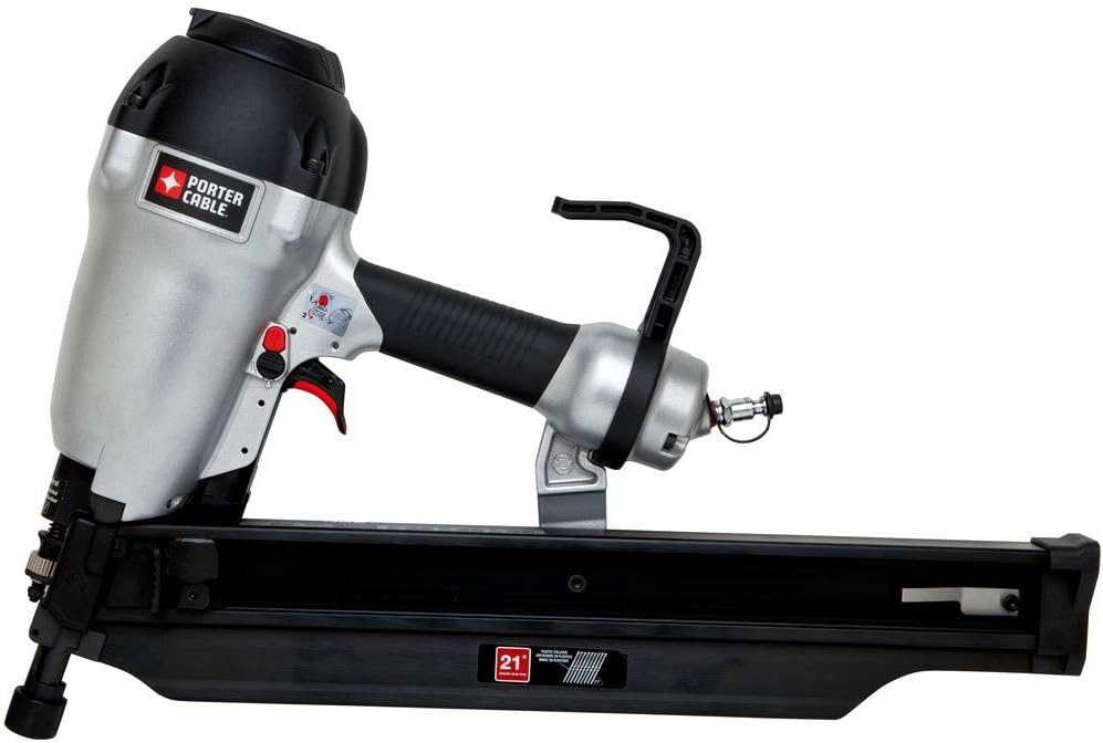
Figure 1: PORTER-CABLE FR350B Framing Nailer. This image shows the overall design of the nailer, including the handle, magazine, and air inlet.
2. General Safety Information
Always observe basic safety precautions to reduce the risk of personal injury and damage to the tool. This tool is designed for driving full round head, plastic collated nails.
2.1 Personal Safety
- Eye Protection: Always wear ANSI Z87.1 approved safety glasses with side shields.
- Hearing Protection: Wear hearing protection during operation to prevent noise-induced hearing loss.
- Hand Protection: Wear gloves to protect hands from splinters and debris.
- Foot Protection: Wear non-skid safety footwear.
- Clothing: Do not wear loose clothing or jewelry that could get caught in moving parts.
- Stay Alert: Do not operate the tool when tired or under the influence of drugs, alcohol, or medication.
2.2 Tool Safety
- Air Pressure: Do not exceed the maximum recommended air pressure for the tool. Refer to the specifications section.
- Disconnect Air Supply: Always disconnect the air supply before making adjustments, clearing jams, servicing, or when the tool is not in use.
- Never Point at Others: Never point the tool at yourself or others, even if it is not loaded.
- Proper Use: Use the tool only for its intended purpose. Do not modify the tool.
- Secure Workpiece: Ensure the workpiece is stable and secure before nailing.
- Avoid Accidental Firing: Keep fingers off the trigger when not actively driving a nail.
- Clear Work Area: Keep the work area clean and well-lit. Cluttered or dark areas invite accidents.
3. Product Overview
The PORTER-CABLE FR350B is a lightweight (7.3 lbs) 22-degree framing nailer designed to drive 3-1/2-inch x .131-inch full round, plastic collated nails into engineered lumber. Key features include:
- Selectable Trigger: Allows for restrictive (sequential) or contact (bump) actuation mode with a trigger lockout feature.
- Tool-Free Adjustable Depth of Drive: For precise setting of nail heads.
- Low Nail Lockout: Indicates when the magazine needs reloading and prevents dry firing.
- Over-Molded Grip: Enhances comfort and control during extended use.
- Reversible Rafter Hook: For convenient hanging on either the left or right side.
- Tool-Free Adjustable Exhaust: Directs air away from the user.
4. Setup
4.1 Connecting to Air Supply
- Ensure the air compressor is off and the air hose is depressurized.
- Apply a few drops of pneumatic tool oil into the air inlet of the nailer.
- Connect the air hose to the nailer's air inlet. Ensure a secure connection.
- Set the air compressor pressure to the recommended operating range (typically 70-120 PSI, refer to specifications). Do not exceed 120 PSI.
4.2 Loading Nails
- Disconnect the air supply from the nailer.
- Pull back the pusher assembly until it locks into place.
- Insert a strip of full round, plastic collated nails into the magazine, ensuring the nail heads are properly seated in the channel.
- Release the pusher assembly, allowing it to push the nails forward until they are against the nosepiece.

Figure 2: Magazine and Depth Adjustment. This image highlights the nail magazine for loading and the tool-free depth adjustment knob.
4.3 Adjusting Depth of Drive
The tool features a tool-free adjustable depth of drive for precise nail placement.
- Locate the depth adjustment knob near the nosepiece.
- Rotate the knob to increase or decrease the nail driving depth. Test on a scrap piece of material to achieve the desired depth.
4.4 Selecting Actuation Mode
The FR350B offers two actuation modes: restrictive (sequential) and contact (bump) actuation.
- Restrictive Actuation: For precise nail placement. The trigger must be pulled after the nosepiece is pressed against the workpiece.
- Contact Actuation: For rapid firing. The trigger can be held, and nails are driven each time the nosepiece contacts the workpiece.
To switch modes, locate the selector switch near the trigger. Refer to the markings on the tool for the correct setting.

Figure 3: Trigger and Actuation Selector. This image shows the trigger mechanism and the switch for selecting between restrictive and contact actuation modes.
5. Operating Instructions
5.1 Before Operation
- Ensure all safety precautions are followed.
- Verify the air pressure is within the recommended range.
- Check that the magazine is loaded correctly.
- Confirm the desired depth of drive and actuation mode are set.
5.2 Driving Nails
- Hold the tool firmly with both hands.
- Place the nosepiece squarely against the workpiece where the nail is to be driven.
- For Restrictive Actuation: Press the nosepiece firmly against the workpiece, then pull the trigger.
- For Contact Actuation: Pull and hold the trigger, then press the nosepiece firmly against the workpiece to drive a nail. Lift and repeat for subsequent nails.
- The low nail lockout feature will prevent the tool from firing when the magazine is nearly empty, indicating it's time to reload.
5.3 Using the Rafter Hook
The reversible rafter hook allows for convenient temporary storage of the tool.
- To reverse the hook, loosen the screw holding it in place, flip the hook to the desired side, and re-tighten the screw.
- Hang the tool securely on a rafter, joist, or belt when not in immediate use.

Figure 4: Reversible Rafter Hook. This image shows the rafter hook, which can be adjusted for left or right-handed use.
6. Maintenance
Regular maintenance ensures optimal performance and extends the life of your tool.
6.1 Daily Maintenance
- Lubrication: Apply 5-10 drops of pneumatic tool oil into the air inlet at the beginning of each workday or every few hours of continuous use. Do not over-oil.
- Inspect Air Hose: Check the air hose for wear, cuts, or leaks. Replace damaged hoses immediately.
- Clean Tool: Wipe down the tool with a clean, dry cloth to remove dust and debris.
6.2 Periodic Maintenance
- Check Fasteners: Periodically check all screws and fasteners for tightness. Tighten as necessary.
- Inspect Nosepiece and Driver Blade: Check for wear or damage. Replace if necessary.
- Air Filter: If your air compressor has an inline air filter, clean or replace it regularly according to the compressor manufacturer's instructions.
7. Troubleshooting
This section addresses common issues you might encounter with your framing nailer.
| Problem | Possible Cause | Solution |
|---|---|---|
| Nailer does not fire | No air supply; Low air pressure; Trigger lockout engaged; No nails in magazine; Nosepiece not fully depressed | Connect air supply; Increase air pressure; Disengage trigger lockout; Load nails; Ensure nosepiece is fully depressed against workpiece |
| Nails jam frequently | Incorrect nail size/type; Damaged nails; Worn driver blade/nosepiece; Insufficient lubrication; Low air pressure | Use correct nails (22-degree, full round, plastic collated); Replace damaged nails; Inspect and replace worn parts; Lubricate tool; Increase air pressure |
| Nails not driven to full depth | Low air pressure; Depth adjustment set too shallow; Hard material | Increase air pressure; Adjust depth of drive deeper; Use appropriate nails for material hardness |
| Air leaks from tool | Loose fittings; Worn O-rings/seals | Tighten air fittings; Consult a qualified service technician for seal replacement |
8. Specifications
| Feature | Specification |
|---|---|
| Model Number | FR350B |
| Nail Type | 22-degree, Full Round Head, Plastic Collated |
| Nail Length Capacity | 3-1/2 inches |
| Operating Pressure | 70-120 PSI (pounds per square inch) |
| Item Weight | 7.3 pounds |
| Product Dimensions | 21 x 5 x 15 inches |
| Power Source | Air-powered |
| Included Components | 3-1/2IN FULL ROUND FRAMING NAILER (Kitbox and oil not included) |
9. Warranty and Support
For detailed warranty information and customer support, please refer to the official documentation included with your product or visit the PORTER-CABLE website. Do not attempt to repair the tool yourself beyond the maintenance steps outlined in this manual, as this may void your warranty and pose safety risks. For service or parts, contact an authorized service center.


