1. Introduction
This manual provides essential information for the MOOG EV800648 Steering Tie Rod End. It covers product overview, installation considerations, functional aspects, maintenance recommendations, and technical specifications. Proper installation and maintenance are crucial for optimal vehicle performance and safety.
2. Product Overview
The MOOG EV800648 is an inner tie rod end designed for specific vehicle applications. It is a critical component of the steering system, connecting the steering rack to the outer tie rod end, and facilitating precise steering control.
2.1. Compatibility
This tie rod end is compatible with the following vehicle models:
- 2010-2017 Chevrolet Equinox
- 2010-2017 GMC Terrain
Important: Before installation, verify part compatibility with your vehicle's year, make, model, engine, and trim specifications to ensure correct fitment.
2.2. Key Features
- Durable Construction: Ball studs are heat-processed to meet or exceed original equipment (OE) requirements, enhancing fatigue strength and inhibiting premature failure.
- Simplified Installation: Features wrench flats on the housing and stud, aiding in easier installation and alignment adjustments.
- Quality Assurance: Undergoes comprehensive testing during design and development phases by MOOG engineers to ensure reliable performance.
- Pre-Applied Thread Locker: Includes pre-applied thread locking compound to simplify installation and prevent self-loosening of fasteners.

A horizontal view of the MOOG EV800648 inner tie rod end, accompanied by a securing nut and a small tube of thread-locking compound. This image displays the complete product package.

This image highlights the wrench flats on the tie rod end's housing and stud, designed to facilitate straightforward installation and alignment adjustments. The securing nut is also shown.
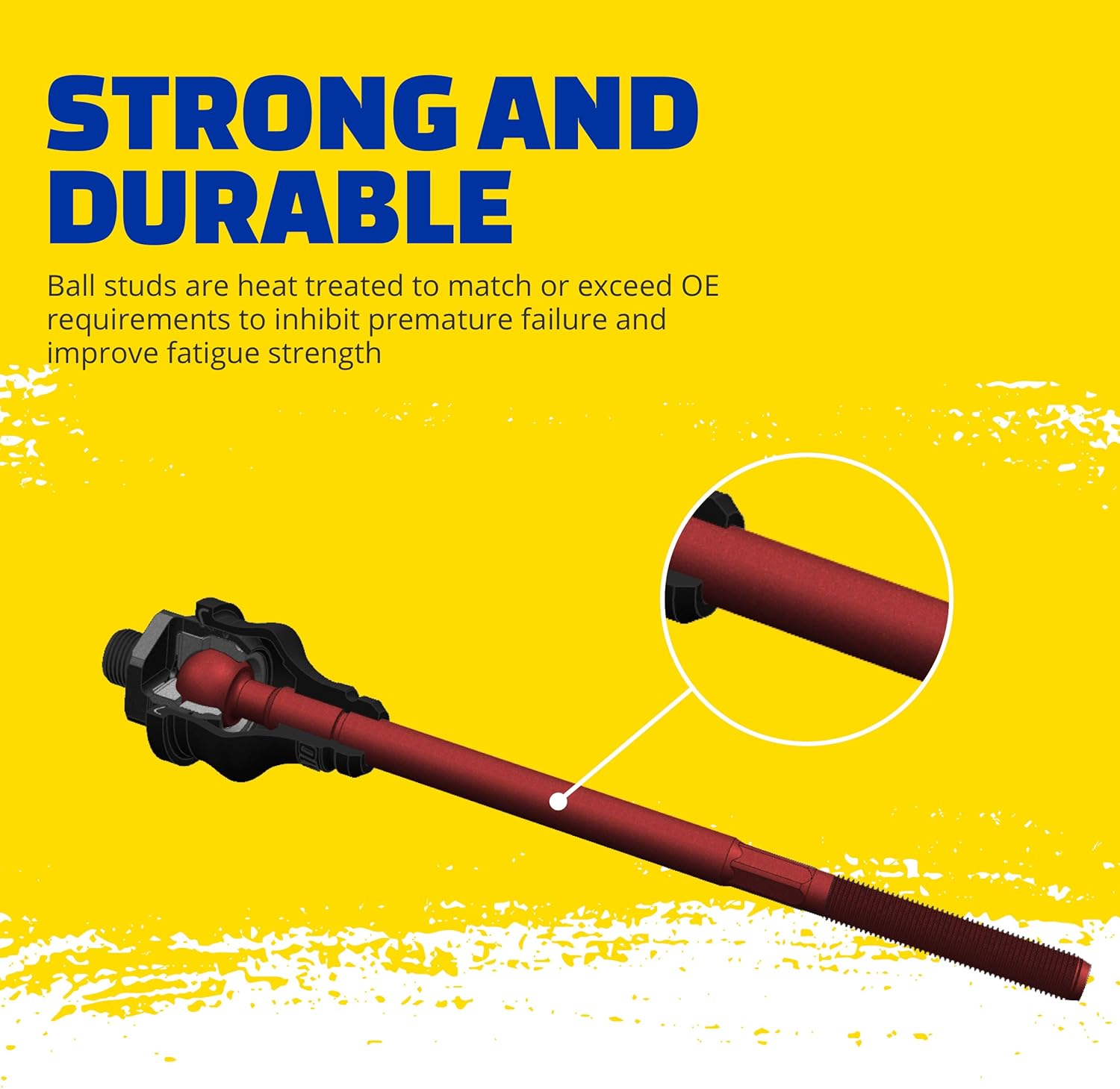
An illustrative diagram emphasizing the robust construction of the tie rod end's ball stud. It shows the heat-treated ball stud, designed to meet or exceed original equipment (OE) requirements for enhanced durability and fatigue strength.
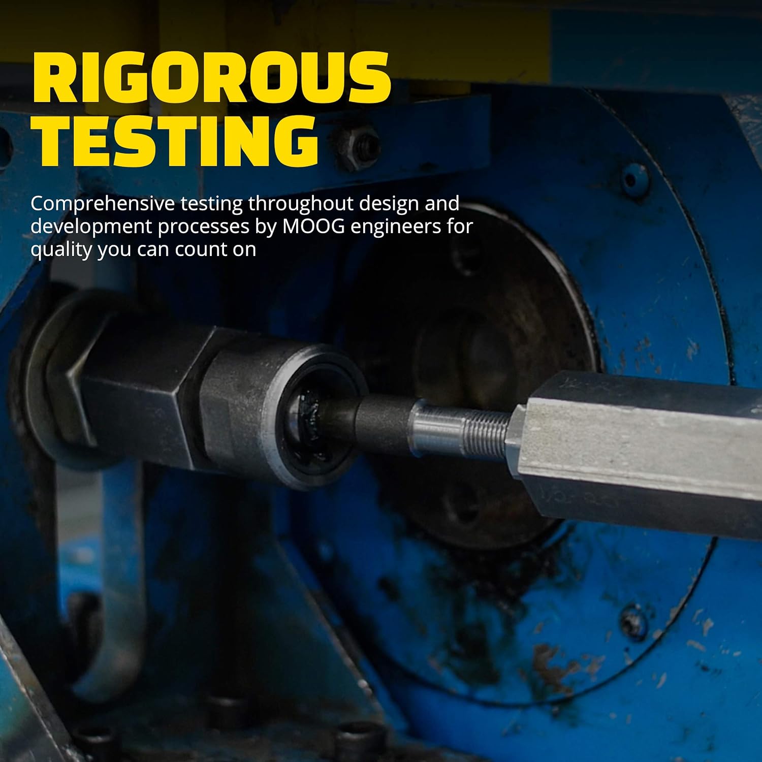
A photograph depicting the MOOG tie rod end being subjected to comprehensive testing procedures within a manufacturing facility. This illustrates the rigorous quality assurance processes applied during design and development.
3. Installation Guidelines
Installation of steering and suspension components requires specialized tools and knowledge. It is highly recommended that this component be installed by a qualified automotive technician.
3.1. Pre-Installation Checks
- Ensure the vehicle is safely supported on jack stands or a lift.
- Confirm the new MOOG EV800648 tie rod end matches the removed component.
- Inspect surrounding components (e.g., steering rack, outer tie rod end, boots) for wear or damage.
3.2. General Installation Steps (Consult a Service Manual for Specifics)
- Loosen the jam nut on the outer tie rod end.
- Carefully count and record the number of turns required to remove the outer tie rod end from the inner tie rod end. This helps in setting initial alignment.
- Remove the boot clamps and slide the steering rack boot off.
- Using an appropriate inner tie rod removal tool, loosen and remove the old inner tie rod end.
- Thread the new MOOG EV800648 inner tie rod end onto the steering rack. Utilize the wrench flats for proper tightening. The pre-applied thread locker will secure the connection.
- Reinstall the steering rack boot and secure it with new clamps.
- Thread the outer tie rod end back onto the new inner tie rod end, matching the recorded number of turns.
- Tighten the jam nut.
3.3. Post-Installation
After installation, a professional wheel alignment is mandatory to ensure correct steering geometry and prevent premature tire wear. Failure to perform an alignment can lead to unsafe driving conditions.

A diagram illustrating the position of an inner tie rod end as part of a vehicle's steering and suspension assembly. It helps visualize where the component is installed and its relation to other parts.
4. Function and Performance
The inner tie rod end is a crucial link in your vehicle's steering system. It translates the rotational motion of the steering rack into linear motion, which then moves the outer tie rod end and ultimately the steering knuckle, allowing the wheels to turn. A properly functioning tie rod end ensures precise steering response and vehicle stability.
4.1. Signs of Wear or Failure
Worn or failing tie rod ends can compromise steering control and vehicle safety. Be aware of the following symptoms:
- Uneven Tire Wear: Irregular wear patterns on tires, particularly on the inner or outer edges.
- Vehicle Pulling: The vehicle drifts or pulls to one side, requiring constant steering correction.
- Steering Wheel Vibration: A noticeable vibration or looseness felt through the steering wheel, especially at higher speeds.
- Clunking Noises: Audible clunking or knocking sounds from the front suspension, particularly when turning or driving over bumps.

Symptom 1: Uneven Tire Wear

Symptom 2: Vehicle Pulling

Symptom 3: Steering Wheel Vibration

Symptom 4: Clunking Noise
5. Maintenance
Regular inspection of steering and suspension components is essential for vehicle safety and longevity. During routine vehicle maintenance, have a qualified technician inspect the tie rod ends for:
- Boot Integrity: Check for tears, cracks, or damage to the protective boot, which can allow contaminants to enter the joint.
- Play/Looseness: With the vehicle lifted, check for excessive play in the tie rod end by attempting to move the wheel horizontally.
- Corrosion: Inspect for signs of rust or corrosion on the component.
Address any signs of wear or damage promptly to maintain steering precision and prevent further component damage.
6. Troubleshooting
If you experience any of the symptoms listed in Section 4.1, or encounter issues during installation, consider the following:
- Installation Difficulty: If the tie rod end is difficult to install or tighten, ensure you are using the correct specialized tools (e.g., an inner tie rod removal tool with the appropriate hex size). Improper tools can damage the component or prevent proper tightening.
- Persistent Symptoms After Replacement: If symptoms persist after replacing the tie rod end, other steering or suspension components may also be worn or damaged. A comprehensive inspection by a professional is recommended.
- Alignment Issues: Always perform a professional wheel alignment after replacing tie rod ends to correct steering angles and prevent tire wear.
7. Specifications
| Attribute | Value |
|---|---|
| Brand | MOOG |
| Model Number | EV800648 |
| Item Weight | 1.81 pounds |
| Product Dimensions | 13.5 x 2 x 2 inches |
| Connector Type | Tie |
| Terminal | Tie Rod |
| Material | Non-Insulated (referring to boot material) |
| UPC | 080066017174 |
| Manufacturer | MOOG Chassis Products |
8. Support and Warranty
For technical assistance, installation questions, or warranty information, please contact MOOG customer support directly. Refer to the official MOOG website or product packaging for the most current contact details and warranty terms.
MOOG products are backed by a commitment to quality and performance. Keep your purchase receipt for any warranty claims.


