1. Introduction
The MFJ-266 Antenna Analyzer is a high-performance instrument designed for amateur radio enthusiasts. It provides comprehensive analysis capabilities for antennas across a wide frequency range, from HF to V/UHF bands. This device offers digital display of measurement values and is known for its simple operation, making it an essential tool for antenna tuning and optimization.
2. Product Overview
Familiarize yourself with the various components and controls of your MFJ-266 Antenna Analyzer.
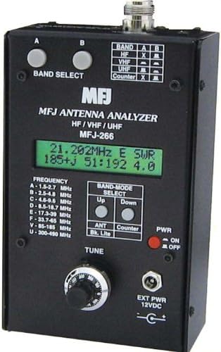
Figure 1: Front Panel of the MFJ-266 Antenna Analyzer. This image shows the main display, band select buttons, tune knob, power switch, and various connectors and indicators.
Key Controls and Indicators:
- Band Select Buttons (A, B): Used to select the desired frequency band for analysis.
- Digital Display: Shows frequency, SWR, impedance (R+jX), and other measurement values.
- Frequency Range Table: Lists the frequency ranges for each band (A-U).
- A: 1.5-2.7 MHz
- B: 2.5-4.8 MHz
- C: 4.8-9.5 MHz
- D: 8.5-18.7 MHz
- E: 17.3-39 MHz
- F: 33.7-65 MHz
- V: 85-185 MHz
- U: 300-490 MHz
- Band-Mode Select (Up/Down): Adjusts the band or mode settings.
- ANT/Bk. Lite Button: Toggles antenna mode or backlight.
- Counter Button: Activates the frequency counter mode.
- PWR (ON/OFF) Switch: Main power switch for the unit.
- TUNE Knob: Fine-tunes the frequency within the selected band.
- EXT PWR 12VDC Input: Connector for external 12V DC power supply.
- N-J Type Connector: Main antenna input connector. An M-type conversion connector is included.
3. Setup
- Power Source:
- Internal Batteries: Insert 8 AA alkaline batteries into the battery compartment, observing correct polarity.
- External Power: Connect a regulated 12V DC power supply to the "EXT PWR 12VDC" input jack. Ensure the power supply can provide sufficient current (refer to specifications).
- Antenna Connection: Connect the antenna to be analyzed to the N-J type connector on the top of the unit. If your antenna uses an M-type connector, use the provided M-type conversion connector.
- Power On: Flip the "PWR" switch to the "ON" position. The digital display should illuminate.
4. Operating Instructions
4.1. Antenna Analysis Mode
- Select Band: Press the "BAND SELECT" buttons (A or B) to cycle through the available frequency bands (A-U) until the desired band is selected. The selected band will be indicated on the display or by an indicator.
- Tune Frequency: Rotate the "TUNE" knob to adjust the operating frequency within the selected band. Observe the frequency reading on the digital display.
- Read Measurements: The digital display will show real-time measurements including:
- Frequency (e.g., 21.202 MHz)
- SWR (Standing Wave Ratio)
- Impedance (R+jX, where R is resistance and X is reactance)
- Magnitude of Impedance (Z)
- Backlight: Press the "ANT/Bk. Lite" button to toggle the display backlight on or off for improved visibility in different lighting conditions.
4.2. Frequency Counter Mode
The MFJ-266 can also function as a standalone frequency counter.
- Activate Counter Mode: Press the "Counter" button. The display will switch to frequency counter mode.
- Input Signal: Connect the signal source you wish to measure to the antenna input connector.
- Read Frequency: The display will show the frequency of the input signal. The frequency counter range is DC to 500 MHz.
5. Maintenance
- Cleaning: Use a soft, dry cloth to clean the exterior of the unit. Do not use abrasive cleaners or solvents.
- Battery Replacement: If using internal batteries, replace all 8 AA batteries when the display dims or the unit behaves erratically. Always use fresh alkaline batteries.
- Storage: Store the analyzer in a cool, dry place away from direct sunlight and extreme temperatures. Remove batteries if storing for extended periods to prevent leakage.
- Connector Care: Keep the antenna connector clean and free of debris. Avoid overtightening connections.
6. Troubleshooting
Common Issues and Solutions:
- Unit does not power on:
- Check battery installation and ensure batteries are fresh.
- If using external power, verify the power supply is connected correctly and providing 12V DC.
- Ensure the PWR switch is in the ON position.
- Display is dim or unreadable:
- Replace batteries if using internal power.
- Press the "ANT/Bk. Lite" button to activate the backlight.
- Inaccurate SWR readings:
- Ensure the antenna connector is clean and securely attached.
- Verify that the correct frequency band is selected for your antenna.
- Check the antenna itself for any damage or issues.
- No frequency counter reading:
- Ensure the "Counter" mode is activated.
- Verify the input signal is within the DC-500 MHz range and has sufficient strength.
7. Specifications
| Feature | Detail |
|---|---|
| Input Impedance | 50Ω |
| VSWR Measurement Range | 1:1 to 99:1 |
| Measurement Frequency Range | 1.5 - 490 MHz (8 range divisions) |
| RF Resistance Measurement Range | 10 - 500Ω |
| Frequency Counter Measurement Range | DC - 500 MHz |
| Connector Type | N-J type (with M-type conversion connector) |
| Power Source | 8 AA alkaline batteries or DC 12V external power |
| Current Consumption (Counter Mode) | 30mA |
| Current Consumption (Analyzer Mode) | 140mA |
| Manufacturer | MFJ |
| Model Number | MFJ-266 |
| Package Dimensions | 24 x 14.8 x 12.4 cm |
| Weight | 780.18 g |
8. Warranty and Support
For warranty information and technical support, please refer to the documentation provided with your purchase or contact your local MFJ distributor. Specific warranty terms may vary by region and retailer.
For further assistance, you may visit the official MFJ website or contact their customer service department.


