1. Introduction
This manual provides detailed instructions for the installation, operation, and maintenance of your White-Rodgers 1F82-0261 Emerson Programmable Heat Pump Thermostat. This device is designed to control your heating and cooling system, offering programmable settings for optimal comfort and energy efficiency.
Key features include a 2-inch backlit display, 5+1+1 day programming, and compatibility with 24-volt or millivolt heat pump systems (2 Heat/1 Cool).
What's in the Box:
- Thermostat Unit
- Instruction Guide (this document)

Figure 1: Front view of the White-Rodgers 1F82-0261 Thermostat, showing the display and control buttons.
2. Setup and Installation
2.1 Safety Precautions
- WARNING: Turn off power to the heating/cooling system at the main fuse or circuit breaker panel before installing or servicing the thermostat.
- Read all instructions carefully before proceeding with installation.
- Installation should be performed by a qualified technician if you are unsure about any steps.
2.2 Wiring
The thermostat is designed for 24-volt or millivolt heat pump systems (2 Heat/1 Cool). It can be hardwired or battery-powered. Ensure proper wiring connections to the terminals.
Terminal Designations:
- R: 24V AC (Heating/Cooling Power)
- C: Common (24V AC Common)
- G: Fan Relay
- Y: Compressor Contactor (Cooling)
- W2: Auxiliary/Emergency Heat
- O/B: Reversing Valve (Heat Pump)
- L: System Monitor (Optional)
Refer to your heat pump system's manual for specific wiring diagrams. Connect wires securely to the corresponding terminals on the thermostat base.
2.3 Initial Configuration
After wiring and restoring power, the thermostat will power on. You may need to set the current time and day. Consult the full installation guide for advanced installer settings, such as system type configuration.
3. Operating Instructions
3.1 Display Overview
The thermostat features a clear 2-inch blue backlit display that shows the current time, temperature, system mode, and fan status. Buttons below the display allow for mode selection and programming.
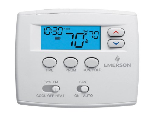
Figure 2: Close-up of the thermostat display and control buttons for operation.
3.2 System Modes
Use the "SYSTEM" switch located at the bottom left of the thermostat to select the desired operating mode:
- COOL: The thermostat will operate your cooling system.
- OFF: The heating and cooling system is turned off.
- HEAT: The thermostat will operate your heating system.
- EMERGENCY (EM HEAT): Activates the auxiliary/emergency heating system, typically used when the heat pump is not functioning or during extreme cold.
- AUTO: The thermostat automatically switches between heating and cooling to maintain the set temperature.
3.3 Fan Modes
Use the "FAN" switch located at the bottom right of the thermostat to select the desired fan operation:
- AUTO: The fan runs only when the heating or cooling system is actively operating.
- ON: The fan runs continuously, regardless of whether the heating or cooling system is active.
3.4 Programming Schedule (5+1+1 Day)
The thermostat allows for 5+1+1 day programming, meaning you can set one schedule for weekdays, one for Saturday, and one for Sunday. This allows for four time periods per day (Wake, Leave, Return, Sleep).
- Press the PRGM button to enter programming mode.
- Use the TIME button to advance through the program periods (Wake, Leave, Return, Sleep) and days (Mon-Fri, Sat, Sun).
- Use the Up and Down arrow buttons to adjust the start time and temperature for each period.
- Press RUN/HOLD to exit programming mode and activate the schedule.
For detailed programming steps, refer to the full instruction guide.
3.5 Temperature Adjustment
To temporarily adjust the temperature, use the Up and Down arrow buttons on the right side of the display. The new temperature will be maintained until the next programmed period begins or until you press RUN/HOLD to cancel the temporary hold.
To permanently hold a temperature, adjust the temperature and then press the RUN/HOLD button until "HOLD" appears on the display. Press RUN/HOLD again to resume the program.
3.6 Energy Management Recovery
This feature allows the thermostat to activate the heating or cooling system prior to a programmed time period to ensure the desired temperature is reached by the start of that period. For example, if you set your "Wake" temperature to 70°F at 6:00 AM, the thermostat might start heating at 5:30 AM to achieve 70°F by 6:00 AM.
4. Maintenance
4.1 Battery Replacement
If your thermostat is battery-powered, replace the batteries when the low battery indicator appears on the display. Typically, two AA alkaline batteries are required. Open the battery compartment, remove old batteries, insert new ones observing polarity, and close the compartment.
4.2 Cleaning
Clean the thermostat's exterior with a soft, damp cloth. Do not use abrasive cleaners or solvents. Avoid spraying liquids directly onto the thermostat.
5. Troubleshooting
- No Display/No Power:
Check if the main power to the HVAC system is on. If battery-powered, replace batteries. Verify wiring connections are secure.
- System Not Responding (No Heating/Cooling):
Ensure the system switch is set to HEAT or COOL (not OFF). Check circuit breakers for the HVAC system. Verify correct wiring. Allow a few minutes for the system to respond after changing settings.
- Incorrect Temperature Reading:
Ensure the thermostat is not exposed to direct sunlight, drafts, or heat sources that could affect its sensor. Recalibration may be required (refer to advanced settings in the full manual).
- Programming Issues:
Double-check that the current time and day are set correctly. Ensure you have pressed RUN/HOLD to activate the program after making changes. If a temporary hold is active, cancel it by pressing RUN/HOLD.
6. Specifications
| Model Number | 1F82-0261 |
| Display | 2-inch Blue Backlit Digital Display |
| System Type | Heat Pump (2 Heat / 1 Cool) |
| Programming | 5+1+1 Day Programmable (4 periods/day) |
| Power Source | 24 Volts AC or Millivolt (Hardwired or Battery) |
| Temperature Range | 45°F to 90°F (7°C to 32°C) |
| Terminals | R, C, G, Y, W2, O/B, L |
| Dimensions | Approximately 2 x 6.5 x 4.5 inches (H x W x D) |
| Manufacturer | White-Rodgers / Emerson |
7. Warranty and Support
For warranty information and technical support, please refer to the documentation provided with your purchase or contact Emerson customer service directly. Keep your proof of purchase for warranty claims.
Manufacturer: White-Rodgers / Emerson