
1. Introduction
This manual provides instructions for the safe and effective operation of the Voltcraft VC155 Digital Hand-held Multimeter. The VC155 is designed for measuring and displaying electrical parameters within the CAT III 600V category. It offers functions for measuring direct and alternating voltage, resistance, acoustic continuity, diode testing, non-contact 230V/AC voltage testing, electric current (10A, mA, µA), and K-type temperature measurement.
Please read this manual thoroughly before using the device to ensure proper handling and to prevent potential hazards.
2. Safety Information
Observe all safety precautions to prevent electric shock, injury, or damage to the meter or the equipment under test.
- The device is rated for Measurement Category CAT III 600V. Do not exceed these limits.
- Always ensure the test leads are in good condition and properly connected before making measurements.
- Do not attempt to measure voltage or current on circuits exceeding the specified maximum input values.
- The two measuring inputs are secured against overload. The voltage in the measuring circuit must not exceed 600V.
- This digital multimeter is equipped with ceramic high-performance fuses for protection. Do not bypass or use incorrect fuses.
- Only operate the device with a 9V block battery. Ensure correct polarity during installation.
- Do not use the meter if it appears damaged or if the battery cover is not properly closed.
- Avoid working alone when performing high-voltage measurements.
- Keep hands and fingers behind the probe barriers during measurements.
3. Product Features and Components

Figure 3.1: Front view of the Voltcraft VC155 Digital Multimeter with connected test leads.

Figure 3.2: Side view of the Voltcraft VC155 Digital Multimeter with its integrated kickstand extended for hands-free operation.
Key Features:
- Display: 2000 counts digital display.
- Measurement Range: Manual range selection.
- Hold Function: Freezes the displayed measurement value.
- Backlight Function: Illuminates the display for use in low-light conditions.
- Torch Function: Integrated flashlight for illuminating the work area.
- Non-Contact Voltage (NCV) Test: Detects AC voltage without direct contact.
- Robust Design: 2-component housing with soft rubber protection for durability and grip.
Components:
- LCD Display: Shows measurement values, units, and function indicators.
- HOLD Button: Toggles data hold function.
- BACK LIGHT Button: Activates/deactivates display backlight and torch.
- Rotary Switch: Selects measurement functions and ranges.
- COM Input Jack: Common (negative) input for all measurements.
- VΩmAµA Input Jack: Positive input for voltage, resistance, diode, continuity, and small current measurements.
- 10A max Input Jack: Positive input for high current (up to 10A) measurements.
- Non-Contact Voltage (NCV) Sensor: Located at the top of the meter.
4. Setup
4.1 Battery Installation
The Voltcraft VC155 requires one 9V block battery for operation. The battery is included with the device.
- Ensure the multimeter is turned OFF.
- Locate the battery compartment on the rear of the device.
- Unscrew the retaining screw(s) and remove the battery cover.
- Connect the 9V battery to the battery clips, observing correct polarity (+ and -).
- Place the battery into the compartment and replace the cover, securing it with the screw(s).
4.2 Test Lead Connection
Proper connection of test leads is crucial for accurate and safe measurements.
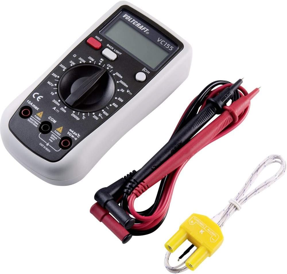
Figure 4.1: Voltcraft VC155 Multimeter showing connected test leads and the K-type temperature sensor.
- Always connect the black test lead to the COM input jack.
- For voltage, resistance, diode, continuity, and small current (mA/µA) measurements, connect the red test lead to the VΩmAµA input jack.
- For high current (up to 10A) measurements, connect the red test lead to the 10A max input jack.
- Ensure connections are firm and secure.
4.3 Temperature Sensor Connection
To measure temperature, use the provided K-type temperature sensor.
- Connect the K-type temperature sensor's plug into the VΩmAµA and COM input jacks, observing polarity (positive to VΩmAµA, negative to COM).
5. Operating Instructions
Turn the rotary switch to the desired function to power on the multimeter. Turn it to the "OFF" position to power off.
5.1 DC Voltage Measurement (V=)
- Set the rotary switch to the desired "V=" range (e.g., 200mV, 2V, 20V, 200V, 600V).
- Connect the red test lead to the VΩmAµA jack and the black test lead to the COM jack.
- Connect the test probes in parallel across the component or circuit to be measured.
- Read the voltage value on the display.
5.2 AC Voltage Measurement (V~)
- Set the rotary switch to the desired "V~" range (e.g., 200V, 600V).
- Connect the red test lead to the VΩmAµA jack and the black test lead to the COM jack.
- Connect the test probes in parallel across the AC voltage source.
- Read the voltage value on the display.
5.3 DC Current Measurement (A=)
- CAUTION: Never connect the meter in parallel with a voltage source when measuring current. This can blow the fuse or damage the meter.
- Set the rotary switch to the desired "A=" range (e.g., 200µA, 2mA, 20mA, 200mA, 10A).
- For µA/mA ranges, connect the red test lead to the VΩmAµA jack. For 10A range, connect the red test lead to the 10A max jack. Connect the black test lead to the COM jack.
- Open the circuit where current is to be measured and connect the meter in series.
- Read the current value on the display.
5.4 Resistance Measurement (Ω)
- Set the rotary switch to the desired "Ω" range (e.g., 200Ω, 2kΩ, 20kΩ, 200kΩ, 2MΩ, 20MΩ).
- Connect the red test lead to the VΩmAµA jack and the black test lead to the COM jack.
- Ensure the circuit or component is de-energized before measuring resistance.
- Connect the test probes across the component.
- Read the resistance value on the display.
5.5 Continuity Test (•))))
- Set the rotary switch to the "•)))" position.
- Connect the red test lead to the VΩmAµA jack and the black test lead to the COM jack.
- Ensure the circuit is de-energized.
- Connect the test probes across the circuit or component.
- If continuity exists (resistance below approximately 50Ω), the buzzer will sound. The display will show the resistance value.
5.6 Diode Test (→|)
- Set the rotary switch to the "→|" position.
- Connect the red test lead to the VΩmAµA jack and the black test lead to the COM jack.
- Ensure the diode is disconnected from the circuit.
- Connect the red probe to the anode and the black probe to the cathode of the diode. The display will show the forward voltage drop.
- Reverse the probes. The display should show "OL" (Open Loop) for a good diode.
5.7 Non-Contact Voltage (NCV) Test
- Set the rotary switch to the "NCV" position.
- Hold the top of the multimeter near an AC voltage source (e.g., a live wire or outlet).
- The meter will emit an audible beep and the NCV indicator will light up if AC voltage is detected.
5.8 Temperature Measurement (°C/°F)
- Set the rotary switch to the "°C" or "°F" position.
- Connect the K-type temperature sensor to the VΩmAµA and COM jacks.
- Place the tip of the temperature sensor on or near the object whose temperature is to be measured.
- Read the temperature value on the display.
5.9 HOLD Function
- Press the HOLD button during a measurement to freeze the current reading on the display.
- Press the HOLD button again to release the reading and return to live measurement.
5.10 Backlight and Torch Function
- Press the BACK LIGHT button to activate the display backlight.
- Press and hold the BACK LIGHT button to activate the integrated torch.
- Press the BACK LIGHT button again to turn off the backlight or torch.
6. Maintenance
6.1 Cleaning
- Turn off the meter and disconnect all test leads before cleaning.
- Wipe the case with a damp cloth and a mild detergent. Do not use abrasives or solvents.
- Ensure no moisture enters the meter's casing.
6.2 Battery Replacement
When the battery symbol appears on the display, the 9V battery needs to be replaced.
- Turn off the meter and disconnect all test leads.
- Unscrew the retaining screw(s) on the battery compartment cover on the rear of the device.
- Remove the old battery and replace it with a new 9V block battery, observing correct polarity.
- Replace the battery cover and secure it with the screw(s).
6.3 Fuse Replacement
The current input jacks are protected by ceramic high-performance fuses. If the meter fails to measure current, the fuse may need replacement. Fuse replacement should only be performed by qualified personnel.
- Fuses: F1: F 200mA/250V, F2: F 10A/250V (specific fuse ratings are typically printed near the fuse holder or in a more detailed service manual).
- Always replace with fuses of the exact same type and rating.
7. Troubleshooting
| Problem | Possible Cause | Solution |
|---|---|---|
| No display or dim display | Dead or low battery. | Replace the 9V battery. |
| Incorrect readings | Incorrect function/range selected; poor test lead connection; damaged test leads. | Verify function and range; ensure secure connections; inspect and replace damaged leads. |
| Cannot measure current | Blown fuse in the current input circuit. | Replace the appropriate fuse (refer to Section 6.3). |
| "OL" (Overload) displayed | Measurement exceeds the selected range; open circuit (for resistance/continuity). | Select a higher range; check for open circuits or proper connection. |
8. Specifications
| Parameter | Value |
|---|---|
| Display | 2000 counts |
| Measurement Category | CAT III 600V |
| DC Voltage (V=) | Ranges: 200mV, 2V, 20V, 200V, 600V; Basic Accuracy: 0.5% |
| AC Voltage (V~) | Ranges: 200V, 600V; Basic Accuracy: 0.1V ~600V AC reading range |
| DC Current (A=) | Ranges: 200µA, 2mA, 20mA, 200mA, 10A |
| Resistance (Ω) | Ranges: 200Ω, 2kΩ, 20kΩ, 200kΩ, 2MΩ, 20MΩ; 10MΩ DC resistance, 4.5MΩ AC resistance |
| Continuity Test | Audible buzzer below approx. 50Ω |
| Diode Test | Yes |
| Non-Contact Voltage (NCV) | Yes (230V/AC test) |
| Temperature Measurement | K-type sensor input |
| Power Source | 1 x 9V block battery (included) |
| Dimensions (L x W x H) | 5.91 x 2.95 x 1.5 inches (15.0 x 7.5 x 3.8 cm) |
| Weight | 7.1 ounces (200 grams) |
9. Warranty and Support
Voltcraft products are manufactured to high-quality standards and are subject to strict quality controls. For information regarding warranty terms, technical support, or service, please refer to the documentation provided with your purchase or contact your local Voltcraft dealer or customer service center.
You can also visit the official Voltcraft website for further assistance and product information.


