1. Introduction
This manual provides essential information for the safe and effective operation of your Dawson Tools DSM101N Digital Multimeter with Environmental Tester. This device is designed for measuring various electrical parameters such as AC/DC voltage, AC/DC current, resistance, continuity, and diode testing. Additionally, it integrates environmental sensors for temperature, relative humidity, light intensity, and sound level measurements. Please read this manual thoroughly before use and retain it for future reference.
2. Safety Information
Always adhere to basic safety precautions when using this instrument to reduce the risk of fire, electric shock, or personal injury. Improper use can result in electric shock or damage to the meter.
- Do not apply voltage or current that exceeds the maximum specified limits for the meter.
- Exercise extreme caution when working with voltages above 60V DC or 30V AC RMS. These voltages pose a shock hazard.
- Always disconnect the test leads from the circuit before changing functions or ranges.
- Inspect test leads for damaged insulation or exposed metal before each use. Replace if damaged.
- Do not operate the meter if it appears damaged or if the casing is open.
- Ensure the battery compartment cover is securely closed before operation.
- Use the correct input terminals for the selected measurement function.
- Do not use the meter in wet environments or in the presence of explosive gases or dust.
3. Product Overview
The Dawson Tools DSM101N combines a digital multimeter with environmental testing capabilities. Familiarize yourself with the components shown below.
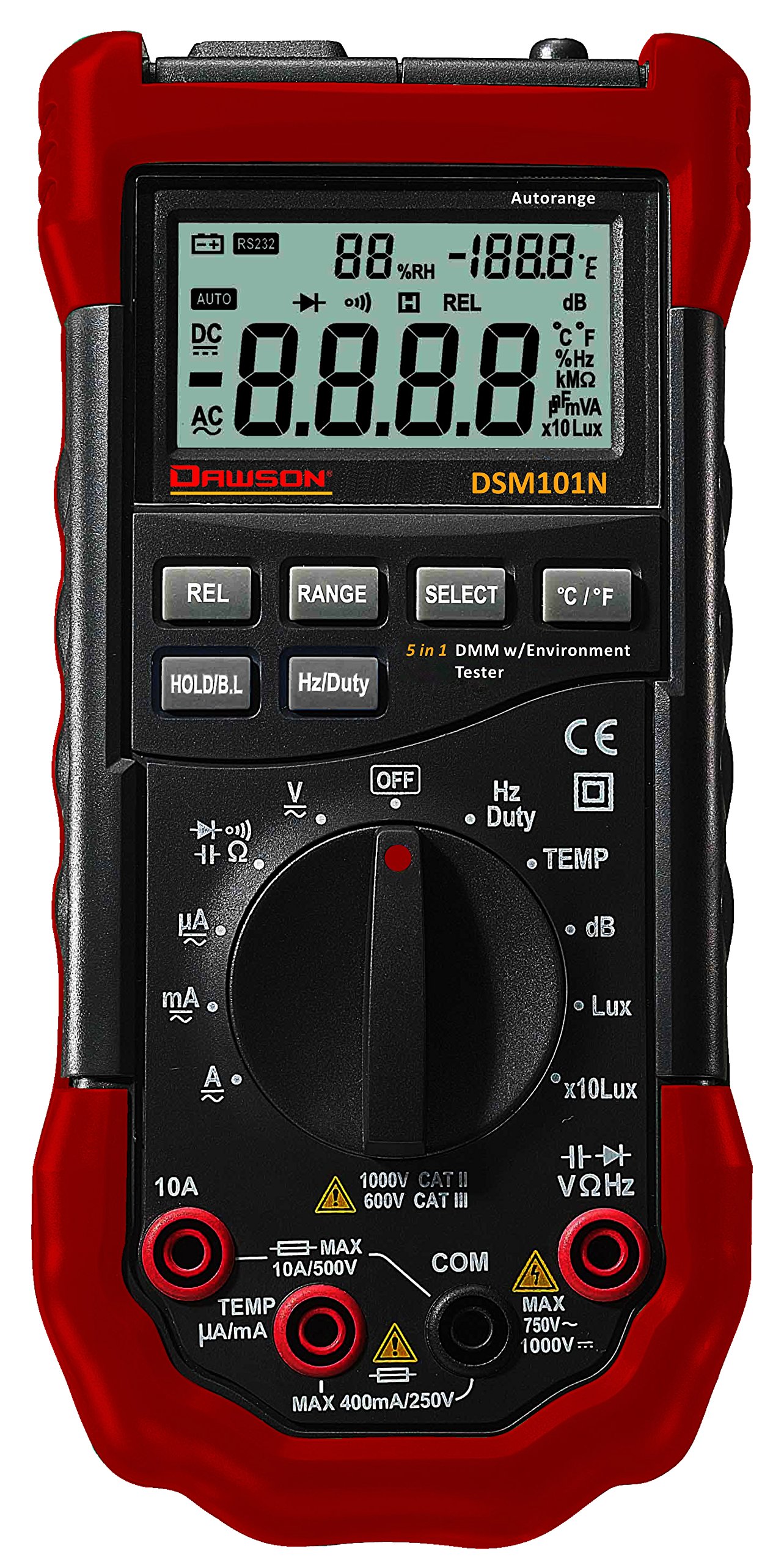
Figure 1: Front view of the Dawson Tools DSM101N Digital Multimeter. This image displays the large LCD screen, the central rotary function dial, the input jacks for test leads at the bottom, and the integrated sensors for environmental measurements (light, sound, temperature, humidity) located at the top of the device.
3.1 Key Components
- LCD Display: Shows measurement readings, units, and function indicators.
- Function Rotary Dial: Used to select the desired measurement function.
- Input Jacks: Terminals for connecting test leads (COM, VΩmA, 10A).
- Environmental Sensors: Integrated sensors for light, sound, temperature, and humidity measurements.
- Function Buttons: Buttons for features like Data Hold, Backlight, Range, etc.
4. Setup
4.1 Battery Installation
The DSM101N is powered by a 9V battery (not included). Follow these steps to install or replace the battery:
- Ensure the meter is turned off and disconnect all test leads.
- Locate the battery compartment cover on the rear of the meter.
- Unscrew the retaining screw(s) and carefully remove the cover.
- Connect a new 9V battery to the battery connector, observing correct polarity.
- Place the battery into the compartment and replace the cover, securing it with the screw(s).
A low battery indicator will appear on the LCD when the battery needs replacement.
5. Operating Instructions
This section details how to perform various measurements using your DSM101N multimeter.
5.1 General Measurement Steps
- Turn the rotary dial to the desired function.
- Connect the test leads to the appropriate input jacks (usually COM and VΩmA for most measurements, or 10A for high current).
- Connect the test leads to the circuit or component under test.
- Read the measurement value on the LCD display.
- Disconnect test leads from the circuit before changing functions or turning off the meter.
5.2 Electrical Measurements
- DC Voltage (V=):
1. Set the rotary dial to the "V=" position.
2. Insert the black test lead into the COM jack and the red test lead into the VΩmA jack.
3. Connect the test leads in parallel across the DC voltage source or component. Observe polarity. - AC Voltage (V~):
1. Set the rotary dial to the "V~" position.
2. Insert the black test lead into the COM jack and the red test lead into the VΩmA jack.
3. Connect the test leads in parallel across the AC voltage source or component. - Resistance (Ω):
1. Set the rotary dial to the "Ω" position.
2. Insert the black test lead into the COM jack and the red test lead into the VΩmA jack.
3. Ensure the circuit is de-energized. Connect the test leads across the component to measure its resistance. - Continuity Test:
1. Set the rotary dial to the continuity/diode position (often indicated by an audible beep symbol).
2. Insert the black test lead into the COM jack and the red test lead into the VΩmA jack.
3. Connect the test leads across the component. A continuous beep indicates continuity (low resistance). - Diode Test:
1. Set the rotary dial to the continuity/diode position (often indicated by a diode symbol).
2. Insert the black test lead into the COM jack and the red test lead into the VΩmA jack.
3. Connect the red lead to the anode and the black lead to the cathode of the diode. The display will show the forward voltage drop. Reverse the leads; the display should show "OL" (Open Loop) for a good diode. - DC Current (A=) / AC Current (A~):
1. Set the rotary dial to the appropriate "A=" or "A~" range (e.g., mA, 10A).
2. For mA/µA, insert the black test lead into the COM jack and the red test lead into the VΩmA jack. For 10A, insert the red test lead into the 10A jack.
3. Crucially, connect the meter in series with the circuit. Break the circuit and insert the meter so that the current flows through it. Never connect in parallel for current measurement.
5.3 Environmental Measurements
- Temperature (Temp):
1. Set the rotary dial to the "Temp" position.
2. The meter will display the ambient temperature using its internal sensor. If an external K-type thermocouple is used (not included), connect it to the designated input ports (often VΩmA and COM, or specific Temp ports if available) and the display will show the external temperature. - Relative Humidity (RH):
1. Set the rotary dial to the "RH" position.
2. The meter will display the relative humidity percentage using its internal sensor. - Light (Lux/Fc):
1. Set the rotary dial to the "Light" position.
2. Point the light sensor (usually located at the top of the meter) towards the light source. The display will show the light intensity in Lux or Foot-candles (Fc). - Sound Level (dB):
1. Set the rotary dial to the "Sound" position.
2. Point the microphone (usually located at the top of the meter) towards the sound source. The display will show the sound level in decibels (dB).
5.4 Special Functions
- Data Hold (HOLD): Press the "HOLD" button to freeze the current reading on the display. Press again to release.
- Backlight: Press the backlight button (often labeled with a light bulb icon) to illuminate the display for better visibility in low-light conditions.
- Range Selection (RANGE): In some functions, the meter may have auto-ranging. Pressing the "RANGE" button can switch between auto-ranging and manual ranging, allowing you to select a specific range.
6. Maintenance
6.1 Cleaning
Wipe the meter's casing with a damp cloth and a mild detergent. Do not use abrasives or solvents. Ensure the meter is completely dry before use.
6.2 Battery Replacement
Refer to Section 4.1 for battery replacement instructions. Replace the battery promptly when the low battery indicator appears to ensure accurate readings.
6.3 Fuse Replacement
If the current measurement function fails, the fuse may need replacement. This procedure should only be performed by qualified personnel.
- Ensure the meter is turned off and all test leads are disconnected.
- Open the battery compartment cover (and potentially the entire back casing, depending on design).
- Locate the fuse(s). Note the type and rating of the blown fuse.
- Replace the fuse with one of the exact same type and rating. Never use a fuse with a different rating.
- Reassemble the meter, ensuring all screws are tightened.
7. Troubleshooting
| Problem | Possible Cause | Solution |
|---|---|---|
| No display or dim display | Dead or low battery | Replace the 9V battery (refer to Section 4.1). |
| "OL" (Overload) displayed | Measurement exceeds selected range or meter's maximum capacity. Open circuit for continuity/resistance. | Select a higher range or ensure proper circuit connection. |
| Incorrect readings | Incorrect function selected, poor test lead connection, or damaged test leads. | Verify function, check lead connections, inspect and replace leads if necessary. |
| Current measurement not working | Blown fuse. | Replace the fuse (refer to Section 6.3). |
8. Specifications
The following are the general specifications for the Dawson Tools DSM101N Digital Multimeter with Environmental Tester. Specifications are subject to change without notice.
- Display: LCD, 3½ digit (1999 counts)
- DC Voltage: Up to 1000V
- AC Voltage: Up to 750V
- DC Current: Up to 10A
- AC Current: Up to 10A
- Resistance: Up to 20MΩ
- Temperature: Range typically -20°C to 1000°C (with K-type thermocouple)
- Relative Humidity: 0% to 100% RH
- Light: Up to 200,000 Lux / 20,000 Fc
- Sound Level: 35dB to 100dB
- Power Source: 9V Battery
- Dimensions (L x W x H): Approximately 19.6 x 9.1 x 5.6 cm (7.7 x 3.6 x 2.2 inches)
- Weight: Approximately 408 g (0.9 lbs)
- Operating Temperature: 0°C to 40°C (32°F to 104°F)
9. Warranty and Support
Dawson Tools products are manufactured to high-quality standards. For warranty information, technical support, or service, please contact your local distributor or the manufacturer directly. Keep your purchase receipt as proof of purchase.
Manufacturer: Dawson Tools