
1. Introduction
The Power Probe III (PP3LS01) is an advanced automotive circuit tester designed to simplify electrical diagnostics. This tool provides the ability to apply power or ground, test continuity, check components, and capture voltage readings, making it an essential device for automotive technicians and enthusiasts. It operates on 12-24V DC systems.
2. Safety Information
Always observe the following safety precautions when using the Power Probe III to prevent injury or damage to the vehicle or tool:
- Wear appropriate eye protection.
- Do not use the tool on AC voltage circuits.
- Ensure proper ventilation when working with automotive batteries.
- Avoid contact with moving engine parts.
- Do not apply power or ground to sensitive electronic components without consulting the vehicle's service manual.
- Keep the tool and accessories clean and dry.
3. Package Contents
The Power Probe PP3LS01 kit includes the following items:
- Power Probe III Unit
- 4mm Leads and Connectors
- Cigarette Lighter Adapter
- 3-Foot Probe Tip
- Battery Hook-Up Clips
- 20-Foot Extension Lead
- Instruction Manual

Image 3.1: Overview of the Power Probe III Lead Set Combo Kit contents.
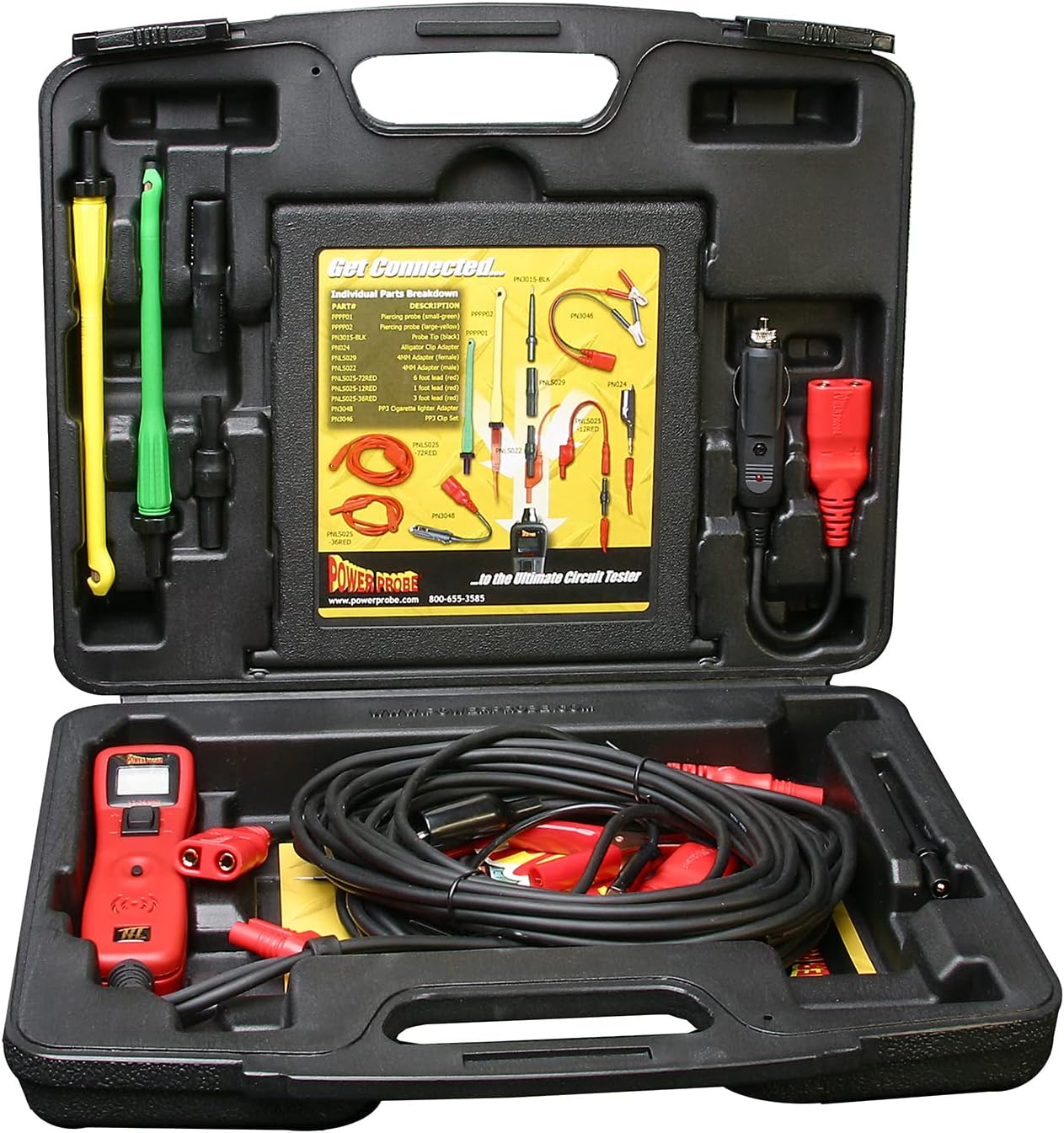
Image 3.2: Power Probe III kit contents neatly arranged in the protective carrying case.
4. Setup
To prepare your Power Probe III for use, follow these steps:
- Connect to Power Source: Attach the red battery clip to the positive (+) terminal of the vehicle's battery and the black battery clip to the negative (-) terminal or a suitable chassis ground. Alternatively, use the cigarette lighter adapter for power.
- Verify Power: Once connected, the Power Probe III's display should illuminate, showing the vehicle's voltage.
- Attach Probe Tip: Securely connect the desired probe tip or extension lead to the Power Probe III unit.

Image 4.1: Proper connection of the Power Probe III to a 12V battery source.
5. Operating Instructions
The Power Probe III offers multiple functions for comprehensive electrical testing:
5.1. Voltage and Polarity Testing
Touch the probe tip to the circuit or component to be tested. The LCD display will show the voltage reading and indicate polarity (positive or negative).
5.2. Power/Ground Activation
To activate a component or circuit, touch the probe tip to the desired point. Press the POWER SWITCH forward for positive voltage or backward for ground. The tool's internal circuit breaker protects against overloads.

Image 5.1: Using the Power Probe III to test a fuse within a vehicle's electrical system.
5.3. Continuity Testing
With the tool powered, touch the probe tip to one end of the circuit or component and connect the auxiliary ground lead to the other end. An audible tone and a green LED indicate continuity.
5.4. Min/Max Voltage Capturing
The Power Probe III can capture minimum and maximum voltage readings. Refer to the unit's display for these values, which are useful for detecting intermittent voltage drops or spikes.
5.5. Relay and Component Testing
The Power Probe III can be used to test various components and relays by applying power or ground directly. Always ensure the component can safely handle the applied voltage and current.
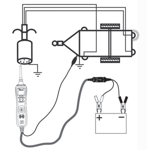
Image 5.2: Example application: Testing trailer lights with the Power Probe III.
6. Maintenance
To ensure the longevity and accuracy of your Power Probe III:
- Clean the probe tip regularly to remove dirt and corrosion.
- Store the tool and accessories in the provided carrying case when not in use.
- Inspect leads and connectors for damage before each use. Replace any frayed or damaged components.
- Do not expose the tool to extreme temperatures or moisture.
7. Troubleshooting
If you encounter issues with your Power Probe III, consider the following:
- No Power/Display: Ensure the battery clips are securely connected to a live 12-24V source and that the internal circuit breaker has not tripped.
- Circuit Breaker Trips Frequently: This indicates an overload. Check the circuit you are testing for shorts or excessive current draw. Reduce the load or investigate the circuit further before reapplying power.
- Inaccurate Readings: Verify that connections are clean and secure. Ensure the probe tip is making good contact with the test point.
8. Specifications
| Specification | Value |
|---|---|
| Brand | Power Probe |
| Model | PP3LS01 |
| Power Source | Corded Electric |
| Operating Voltage | 12-24 Volts DC |
| Item Weight | 4.75 Pounds |
| Product Dimensions (L x W x H) | 3.48 x 11.5 x 3.48 inches |
| Measurement Type | Multimeter |
| Exterior Material | Steel |
9. Manufacturer Information & Support
For additional support, warranty information, or to explore other Power Probe products, please visit the official Power Probe website or contact your retailer.
Brand: Power Probe
Manufacturer: Power Probe
Official Brand Store: Power Probe Store on Amazon

Image 9.1: Power Probe company logo.


