1. Introduction
This manual provides essential instructions for the safe and effective operation, maintenance, and troubleshooting of your Cablematic YF-3700A Digital Multimeter. Please read this manual thoroughly before using the device to ensure proper function and to prevent potential hazards.
2. Safety Information
Always adhere to the following safety precautions to prevent electric shock, injury, or damage to the multimeter or the equipment under test.
- Do not exceed the maximum input limits for any function.
- Ensure the function switch is in the correct position for the measurement being performed.
- Never connect the test leads to a voltage source when the function switch is set to current, resistance, or diode/continuity test.
- Use caution when working with voltages above 30V AC RMS, 42V peak, or 60V DC, as these pose a shock hazard.
- Inspect test leads for damaged insulation or exposed metal before use. Replace if damaged.
- Do not operate the multimeter if it appears damaged or if the case is open.
- Remove test leads from the circuit before opening the battery cover or fuse compartment.
- Always use the proper terminals, function, and range for your measurements.
3. Product Overview
The Cablematic YF-3700A is a digital multimeter designed for measuring various electrical parameters. It features a clear digital display and a rotary switch for function selection.
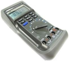
Figure 1: Cablematic YF-3700A Digital Multimeter. This image shows the overall view of the YF-3700A digital multimeter, featuring its grey casing, digital display, function buttons, rotary selector switch, and input jacks.

Figure 2: Cablematic YF-3700A Digital Multimeter Controls. A close-up view of the multimeter's control panel, highlighting the rotary switch with various measurement functions (V, Hz, mA, A, Ohm, Diode, Continuity), push buttons for features like RANGE, HOLD, MIN/MAX, and MEM, and the input terminals (10A, mA, COM, VΩ).
4. Setup
4.1 Battery Installation
The multimeter requires batteries for operation. Ensure the device is powered off and test leads are disconnected before proceeding.
- Locate the battery compartment cover on the rear of the multimeter.
- Use a screwdriver to loosen the screw(s) securing the cover.
- Remove the cover and insert the required batteries, observing correct polarity (+ and -).
- Replace the battery compartment cover and secure it with the screw(s).
4.2 Connecting Test Leads
Connect the test leads to the appropriate input jacks for the desired measurement.
- The COM (common) jack is for the black test lead.
- The VΩ jack is for the red test lead when measuring voltage, resistance, frequency, or performing diode/continuity tests.
- The mA jack is for the red test lead when measuring current up to 400mA.
- The 10A jack is for the red test lead when measuring current up to 10A.
5. Operating Instructions
5.1 Powering On/Off
To power on the multimeter, rotate the function switch from the OFF position to any desired measurement function. To power off, rotate the function switch back to the OFF position.
5.2 Function Selection
Use the central rotary switch to select the desired measurement function (e.g., V for voltage, Ω for resistance, A for current, Hz for frequency, Diode, Continuity).
5.3 Measuring Voltage (AC/DC)
- Insert the black test lead into the COM jack and the red test lead into the VΩ jack.
- Rotate the function switch to the desired AC Voltage (V~) or DC Voltage (V-) range.
- Connect the test probes in parallel across the component or circuit to be measured.
- Read the voltage value on the display.
5.4 Measuring Current (AC/DC)
Caution: Never connect the multimeter in parallel with a voltage source when measuring current. Always connect in series with the load.
- Insert the black test lead into the COM jack.
- For currents up to 400mA, insert the red test lead into the mA jack. For currents up to 10A, insert the red test lead into the 10A jack.
- Rotate the function switch to the desired AC Current (A~) or DC Current (A-) range.
- Open the circuit where current is to be measured and connect the multimeter in series.
- Read the current value on the display.
5.5 Measuring Resistance
- Insert the black test lead into the COM jack and the red test lead into the VΩ jack.
- Rotate the function switch to the Ω (resistance) range.
- Ensure the circuit or component under test is de-energized.
- Connect the test probes across the component.
- Read the resistance value on the display.
5.6 Diode Test
- Insert the black test lead into the COM jack and the red test lead into the VΩ jack.
- Rotate the function switch to the diode symbol.
- Connect the red probe to the anode and the black probe to the cathode of the diode. The display will show the forward voltage drop.
- Reverse the probes. The display should show 'OL' (open loop) for a good diode.
5.7 Continuity Test
- Insert the black test lead into the COM jack and the red test lead into the VΩ jack.
- Rotate the function switch to the continuity symbol.
- Connect the test probes across the circuit or component.
- If continuity exists (resistance below a certain threshold), the multimeter will emit an audible beep.
5.8 Data Hold Function
Press the HOLD button to freeze the current reading on the display. Press it again to release the hold function.
5.9 Range Selection
The multimeter typically operates in auto-ranging mode. To manually select a range, press the RANGE button. Subsequent presses will cycle through available ranges. To return to auto-ranging, press and hold the RANGE button.
6. Maintenance
6.1 Cleaning
Wipe the case with a damp cloth and a mild detergent. Do not use abrasives or solvents. Ensure the multimeter is completely dry before use.
6.2 Battery Replacement
When the battery indicator appears on the display, replace the batteries as described in Section 4.1. Always use the specified battery type.
6.3 Fuse Replacement
If the current measurement function stops working, the fuse may need replacement. Refer to the specifications for the correct fuse type and rating. Ensure the multimeter is powered off and test leads are disconnected before opening the fuse compartment.
7. Troubleshooting
| Problem | Possible Cause | Solution |
|---|---|---|
| No display or dim display | Dead or low batteries | Replace batteries (Section 4.1) |
| Incorrect readings | Incorrect function/range selected; Poor test lead connection; Damaged test leads | Verify function/range; Check lead connections; Replace test leads if damaged |
| Current measurement not working | Blown fuse | Replace fuse (Section 6.3) |
| 'OL' (Overload) displayed | Input exceeds selected range; Open circuit (for resistance/continuity) | Select a higher range; Check circuit for breaks |
8. Specifications
| Parameter | Value |
|---|---|
| Brand | Cablematic |
| Model Number | PN26021410525115347 (YF-3700A) |
| Power Source Type | Battery Powered |
| Item Weight | 1.81 Pounds (approx. 821 g) |
| Package Dimensions | 21 x 13.4 x 6.4 cm |
| Safety Standard | IEC 61326 |
| Global Trade Identification Number | 08433696103472 |
9. Warranty Information
This Cablematic YF-3700A Digital Multimeter is covered by a standard manufacturer's warranty. Please refer to the warranty card included with your purchase or contact Cablematic customer support for detailed terms and conditions. The warranty typically covers defects in materials and workmanship under normal use.
10. Support
For technical assistance, troubleshooting beyond this manual, or warranty claims, please contact Cablematic customer support. Contact details can typically be found on the product packaging or the official Cablematic website.


