1. Introduction
This manual provides essential information for the installation, configuration, and operation of your ASUS P8Z77-V PRO motherboard. This motherboard is designed to support Intel LGA1155 3rd/2nd Generation Intel Core i7/i5/i3/Pentium/Celeron Processors and features the Intel Z77 chipset. Please read this manual thoroughly before proceeding with installation.
2. Product Features
The ASUS P8Z77-V PRO motherboard incorporates several advanced features to enhance your computing experience:
- Wi-Fi GO!: This feature enables comprehensive multimedia management, diverse remote control options, Internet sharing capabilities, and quick data sharing functionalities within your home network.
- Fan Xpert 2: Provides an automatic tuning function for optimized fan speed control and customized settings for each individual fan connected to the system, ensuring efficient cooling and reduced noise.
- ASUS USB 3.0 Boost: Allows users to set USB 3.0 devices into three distinct modes (Normal, Turbo, UASP) to significantly enhance overall read/write performance instantaneously.
- SMART DIGI+ Power Control: Offers flexible and precise adjustments for system stability, high power efficiency, and improved performance scaling for both the CPU and RAM, providing consistent power delivery.
- USB BIOS Flashback: Simplifies BIOS updates by allowing users to plug in a USB drive containing the BIOS file and press a dedicated button. This feature enables BIOS updates even without a CPU or RAM installed.
3. Setup and Installation
Before beginning installation, ensure your workspace is clean and static-free. It is recommended to wear an anti-static wrist strap. Refer to your computer case manual for specific mounting instructions.
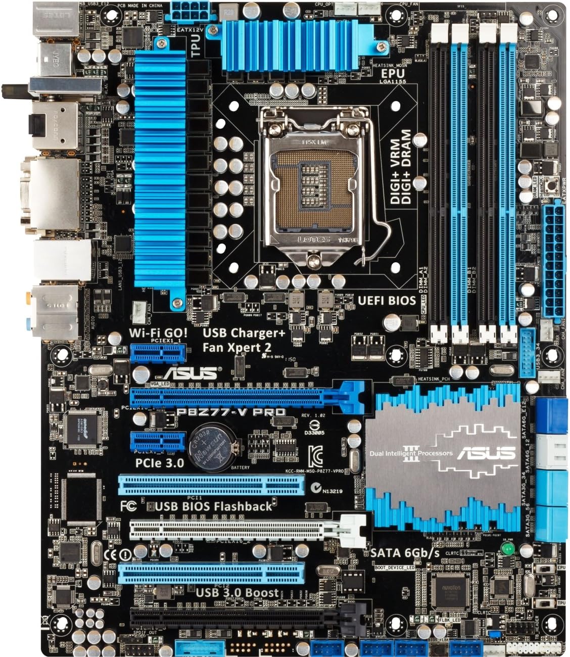
Figure 1: ASUS P8Z77-V PRO Motherboard Layout. This image displays the layout of the ASUS P8Z77-V PRO motherboard. Key components visible include the LGA 1155 CPU socket at the center, four DDR3 DIMM slots to the right, multiple PCIe expansion slots, SATA ports, and various headers for front panel connectors and USB ports. Blue heatsinks are prominent on the VRM and chipset areas.
3.1. CPU Installation
- Carefully open the CPU socket lever.
- Align the CPU with the socket's notch (triangle mark) and gently place it into the socket without forcing it.
- Close the lever to secure the CPU in place.
- Apply a thin, even layer of thermal paste to the CPU's surface.
- Install the CPU cooler according to its manufacturer's instructions.
3.2. Memory (RAM) Installation
- Locate the four DDR3 DIMM slots on the motherboard.
- Open the clips at both ends of the desired DIMM slot.
- Align the memory module with the slot key (notch) and press firmly on both ends until the clips snap into place.
- For optimal performance, refer to the motherboard's Qualified Vendor List (QVL) for compatible memory modules.
- Note: When installing 32GB of RAM, some users have reported that the initial system boot may require starting with less than 32GB, then adding the remaining modules after the first successful boot.
3.3. Motherboard Mounting
- Install the motherboard into your computer case using the provided standoffs and screws. Ensure all mounting holes on the motherboard align with the standoffs in the case.
3.4. Power Connections
- Connect the 24-pin ATX main power connector from your power supply to the corresponding port on the motherboard.
- Connect the 8-pin EATX12V CPU power connector from your power supply to the port near the CPU socket.
3.5. Storage Device Connections
- Connect your SATA 6Gb/s or SATA 3Gb/s storage devices (SSDs/HDDs) to the SATA ports on the motherboard using SATA data cables.
- Connect power from the power supply to these storage devices.
3.6. Expansion Cards
- Insert graphics cards or other PCIe expansion cards into the appropriate PCIe slots.
- Secure them with screws to the case.
3.7. Front Panel Connectors
- Connect the front panel headers (power button, reset button, USB ports, audio jacks, LED indicators) to the corresponding pins on the motherboard. Refer to the motherboard diagram (Figure 1) and your case manual for correct pin assignments.
4. Operating Instructions
4.1. BIOS/UEFI Setup
To access the UEFI BIOS, press the Delete key repeatedly during system startup. The UEFI interface allows for system configuration, boot order adjustment, hardware monitoring, and overclocking settings.
4.2. Driver Installation
After installing your operating system, it is crucial to install the necessary drivers for the motherboard's components. These drivers can be found on the ASUS support website or on the provided driver disc to ensure optimal performance and functionality.
4.3. Utilizing ASUS Software Utilities
Leverage the included ASUS software utilities to manage and optimize your system:
- Fan Xpert 2: Fine-tune fan speeds for optimal cooling and acoustics.
- USB 3.0 Boost: Enhance the data transfer speeds of your USB 3.0 devices.
- Wi-Fi GO!: Manage network connections, share content, and control your PC remotely.
5. Maintenance
5.1. Cleaning
Regularly clean dust from the motherboard and other internal components using compressed air. Ensure the system is powered off and unplugged from the wall outlet before performing any cleaning. Dust accumulation can lead to overheating and reduced component lifespan.
5.2. BIOS Updates
Periodically check the official ASUS support website for the latest BIOS updates. BIOS updates can improve system stability, enhance hardware compatibility, and introduce new features. Utilize the USB BIOS Flashback feature for a convenient and safe update process.
6. Troubleshooting
This section provides solutions for common issues you might encounter.
6.1. No Power or System Fails to Boot
- Verify that all power connections (24-pin ATX, 8-pin EATX12V) are securely seated on the motherboard and connected to the power supply.
- Ensure the power supply unit (PSU) is functional and switched on.
- Check that the CPU and RAM modules are correctly installed and seated.
6.2. POST Code Errors or No Display
- If the system fails to boot and displays a POST code on the motherboard's debug LED, consult the motherboard manual for the meaning of the specific code. Common issues relate to RAM, CPU, or graphics card problems.
- Ensure the graphics card is properly seated in its PCIe slot and connected to auxiliary power if required.
- Verify that the monitor cables are securely connected to the graphics card and the monitor.
6.3. Peripheral Recognition Issues
- If USB devices or other peripherals are not recognized, ensure they are connected to the correct ports and that their respective drivers are installed. Try connecting them to different ports.
6.4. System Instability or Crashes
- Check for overheating components by monitoring temperatures in the BIOS or with system monitoring software. Ensure adequate airflow within the case.
- Ensure all system drivers, especially chipset and graphics drivers, are up to date.
- If experiencing frequent crashes, test memory modules individually to identify a potentially faulty stick.
7. Specifications
| Component | Specification |
|---|---|
| CPU Socket | LGA 1155 |
| Compatible Processors | Intel 3rd/2nd Generation Core i7/i5/i3/Pentium/Celeron Processors |
| Chipset | Intel Z77 |
| Memory | 4 x DIMM, Max. 32GB, DDR3 2600(O.C.)/2400(O.C.)/2200(O.C.)/2133(O.C.)/1866(O.C.)/1600/1333 MHz Non-ECC, Un-buffered Memory |
| Expansion Slots | 2 x PCIe 3.0/2.0 x16 (x16 or x8/x8), 1 x PCIe 2.0 x16 (x4 mode), 4 x PCIe 2.0 x1 |
| Storage | 4 x SATA 6Gb/s ports, 4 x SATA 3Gb/s ports |
| USB Ports | USB 3.0, USB 2.0 |
| Wireless Connectivity | 802.11b/g (via Wi-Fi GO! module) |
| Form Factor | ATX |
| Dimensions | 13.89 x 11.81 x 2.89 inches (Product Dimensions) |
8. Support and Warranty
For technical assistance, driver downloads, BIOS updates, and detailed warranty information, please visit the official ASUS support website. It is recommended to keep your proof of purchase for any warranty claims.
ASUS Support Website: Visit ASUS Support


