1. Introduction
This manual provides essential information for the safe and effective use of the uxcell 3P AC 300V 20A 7.62mm Pitch PCB Screw Terminal Block. This component features a 7.62mm terminal spacing, 3 terminals, and a screw-type connection, designed for PCB mounting. It is widely utilized in various electronic applications, communication equipment, instruments, automatic control systems, domestic appliances, and warning devices.
2. Safety Information
- Always disconnect power before installing, servicing, or removing the terminal block.
- Ensure all wiring complies with local and national electrical codes.
- Do not exceed the rated voltage (AC 300V) or current (20A) to prevent damage or electrical hazards.
- Use appropriate tools for wiring and tightening screws to ensure secure connections.
- Avoid touching live electrical components.
- If you are unsure about any installation steps, consult a qualified electrician or electronics technician.
3. Package Contents
Each package contains:
- 5 x 3P Screw Terminal Blocks
4. Setup and Installation
The uxcell PCB Screw Terminal Block is designed for through-hole mounting on a Printed Circuit Board (PCB).
- Prepare the PCB: Ensure your PCB has appropriate holes spaced at 7.62mm for the terminal block pins.
- Insert the Terminal Block: Carefully align the pins of the terminal block with the corresponding holes on the PCB and insert it.
- Solder the Pins: Securely solder each pin of the terminal block to the PCB using appropriate soldering techniques. Ensure good solder joints for reliable electrical contact.
- Connect Wires: Loosen the screws on the terminal block using a small screwdriver. Insert the stripped end of your wire into the terminal opening.
- Secure Wires: Tighten the screw firmly to secure the wire in place. Gently tug on the wire to confirm it is held securely and cannot be easily pulled out.
Refer to the image below for a visual representation of the terminal block and its components.
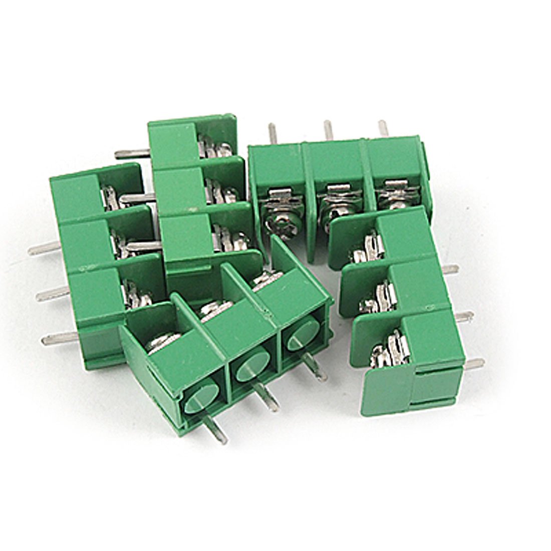
Figure 1: An uxcell 3P AC 300V 20A 7.62mm Pitch PCB Screw Terminal Block. This image shows the green plastic housing, the three screw terminals for wire connection, and the metal pins for PCB mounting. The compact design is evident, highlighting its suitability for various electronic projects.
For a demonstration of the installation process, please watch the following video:
Video 1: This video demonstrates the assembly and soldering of PCB mount screw terminal blocks onto a circuit board. It shows how individual terminal blocks can be combined to form longer strips, how they are inserted into a PCB, and the process of soldering the pins to create a secure electrical connection. The video highlights the practical steps involved in integrating these components into an electronic project.
5. Operating Instructions
Once installed and wired, the terminal block functions as a secure and reliable connection point for electrical circuits. No specific operational steps are required beyond ensuring proper wiring and maintaining the integrity of the connections.
- Wire Connection: Ensure wires are correctly inserted into their respective terminals and the screws are tightened to the appropriate torque to prevent loose connections.
- Circuit Integrity: Verify that the connected circuit operates as intended without any shorts or open circuits.
6. Maintenance
Regular maintenance helps ensure the longevity and reliability of the terminal block.
- Visual Inspection: Periodically inspect the terminal blocks for any signs of physical damage, corrosion, or discoloration.
- Connection Check: Ensure all screw connections remain tight. Over time, vibrations or thermal cycling can cause screws to loosen. Retighten if necessary, but do not overtighten.
- Cleaning: Keep the terminal blocks free from dust, dirt, and moisture. Use a dry, soft cloth for cleaning. Avoid using liquid cleaners that could leave residue or cause corrosion.
7. Troubleshooting
If you encounter issues with your terminal block, consider the following:
- No Electrical Continuity:
- Check if wires are properly stripped and fully inserted into the terminal.
- Ensure screws are tightened securely, making good contact with the wire.
- Inspect solder joints on the PCB for cold joints or bridges.
- Intermittent Connection:
- Retighten all terminal screws.
- Check for any loose or damaged wires.
- Overheating/Discoloration:
- This indicates excessive current or a poor connection. Immediately disconnect power.
- Verify that the current draw does not exceed the 20A rating.
- Ensure all connections are tight and free from corrosion.
8. Specifications
| Product Name | Screw Terminal Block |
| Brand | uxcell |
| Model Number | a11062100ux0013 |
| Material | Plastic |
| Color | Green |
| Rated Voltage | AC 300V |
| Current Rating | 20 Amps |
| Terminal Number | 3 |
| Pitch | 7.62mm (0.3 inches) |
| Connector Type | Screw |
| Mounting Type | PCB Mount |
| Total Size (L*W*H) | 23 x 12 x 17mm (0.9'' x 0.5'' x 0.7'') |
| Item Weight | 0.704 ounces (approx. 20g per 5-pack) |
9. Warranty and Support
For warranty information or technical support regarding your uxcell PCB Screw Terminal Block, please contact the seller or manufacturer directly. Retain your proof of purchase for any warranty claims.
