1. Introduction
This manual provides detailed instructions for the installation, operation, and maintenance of the SDC CB402-B Communicating Bathroom Control and Emergency Access Switch. Please read this manual thoroughly before installation and use to ensure proper function and safety.
2. Product Overview
The SDC CB402-B is a panel-mounted control switch designed for bathroom lock systems, providing both locking/unlocking functionality and emergency access. It features a clear indicator light for lock status.
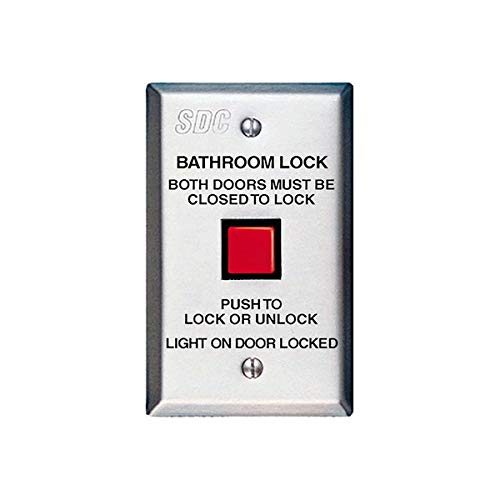
Figure 1: SDC CB402-B Control Panel
This image displays the SDC CB402-B control panel. The panel is rectangular, silver-colored, and features the "SDC" logo at the top. Below the logo, text reads "BATHROOM LOCK" and "BOTH DOORS MUST BE CLOSED TO LOCK". A prominent red square button is located in the center. Below the button, text indicates "PUSH TO LOCK OR UNLOCK" and "LIGHT ON DOOR LOCKED". There are also two visible screws for mounting.
Key Features:
- Integrated lock/unlock button.
- Visual indicator for door lock status.
- Designed for bathroom lock applications requiring two doors to be closed for locking.
- Panel mount design for secure installation.
3. Setup and Installation
Important Safety Information: Installation should only be performed by qualified personnel in accordance with all local electrical codes and regulations. Disconnect power before beginning installation.
- Mounting Location: Select a suitable indoor location for panel mounting, typically adjacent to the door frame or on a wall within easy reach.
- Wiring: The CB402-B requires electrical connections for power and communication with the locking mechanism. Refer to the wiring diagram provided with your specific lock system for correct connections. Ensure all connections are secure and insulated. The unit utilizes an X-10 connectivity protocol for communication, which must be integrated with a compatible system.
- Panel Mounting:
- Prepare the wall opening according to the dimensions specified in the product packaging.
- Feed the necessary wiring through the opening.
- Secure the CB402-B panel to the wall using appropriate screws (as shown in Figure 1). Do not overtighten.
- System Integration: Connect the CB402-B to your bathroom lock system and power supply as per the system's instructions. Verify all connections before restoring power.
- Initial Test: After installation, restore power and perform a functional test to ensure the lock/unlock button and status indicator light operate correctly.
4. Operation
The SDC CB402-B is designed for straightforward operation:
- Locking the Door: To lock the bathroom door(s), ensure "BOTH DOORS MUST BE CLOSED TO LOCK" as indicated on the panel. Press the red square button labeled "PUSH TO LOCK OR UNLOCK".
- Unlocking the Door: To unlock the bathroom door(s), press the red square button again.
- Status Indicator: The panel includes a light indicator. When the "LIGHT ON DOOR LOCKED" is illuminated, it signifies that the door(s) are securely locked.
5. Maintenance
The SDC CB402-B requires minimal maintenance to ensure continued reliable operation:
- Cleaning: Periodically wipe the surface of the control panel with a soft, dry cloth. Avoid using abrasive cleaners or solvents, which can damage the finish or internal components.
- Inspection: Regularly inspect the panel for any signs of physical damage, loose connections, or wear.
- Functionality Check: Periodically test the lock/unlock function and the status indicator light to ensure they are working correctly.
6. Troubleshooting
If you encounter issues with your SDC CB402-B, consider the following:
- Button Not Responding:
- Check if the power supply to the unit and the associated lock system is active.
- Verify all wiring connections are secure and correct according to the installation diagram.
- Ensure both doors are fully closed if the system requires this condition for locking.
- Status Light Not Illuminating:
- Confirm the door is actually locked.
- Check power supply and wiring.
- If the light is still not working, the indicator bulb or LED may need replacement, or there might be an internal fault. Contact SDC support.
- Intermittent Operation: This could indicate loose wiring or an issue with the X-10 communication. Re-check all connections and ensure there is no interference with the X-10 signal.
For persistent issues, contact SDC technical support.
7. Specifications
| Specification | Detail |
|---|---|
| Model | CB402-B |
| Brand | SDC (Security Door Controls) |
| Item Weight | 1 Pound |
| Mounting Type | Panel Mount |
| Connectivity Protocol | X-10 |
| Unit Count | 1 Count |
| Dimensions | 2-7/8 inches W (Width) - Other dimensions not specified. |
8. Warranty and Support
For information regarding the product warranty, please refer to the official SDC (Security Door Controls) website or contact their customer service directly. Warranty terms and conditions may vary.
For technical support or further assistance, please visit the SDC Security website or contact their authorized distributors.


