1. Introduction
This manual provides essential information for the proper installation, operation, and maintenance of your Technical Pro LZ6200 2U Professional 2-Channel Power Amplifier. Please read this manual thoroughly before using the amplifier to ensure optimal performance and safety.
The LZ6200 is a professional-grade 2-channel power amplifier designed for reliable audio amplification in various settings. It features a robust design, versatile input/output options, and a selectable operating voltage of 110V or 220V.
2. Safety Instructions
- Power Source: Ensure the amplifier is connected to a power source matching the selected voltage (110V or 220V) on the rear panel. Incorrect voltage selection can cause severe damage.
- Ventilation: Do not block ventilation openings. Ensure adequate airflow around the unit to prevent overheating. Maintain at least 4 inches (10 cm) of clear space around the amplifier.
- Moisture: Do not expose the amplifier to rain, moisture, or excessive humidity. Keep liquids away from the unit.
- Placement: Place the amplifier on a stable, level surface. Avoid placing it near heat sources or in direct sunlight.
- Servicing: Do not attempt to service this unit yourself. Refer all servicing to qualified service personnel.
- Grounding: Always use a grounded power cord.
3. Package Contents
Verify that your package contains the following items:
- Technical Pro LZ6200 Power Amplifier Unit
- AC Power Cable
- Instruction Manual (this document)
- Key for Front Panel Lock
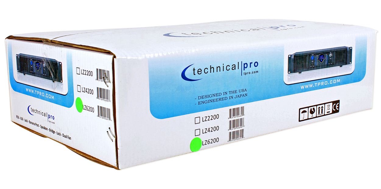
Image: Packaging box for the Technical Pro LZ6200 amplifier, showing the model number and brand logo.
4. Front Panel Features
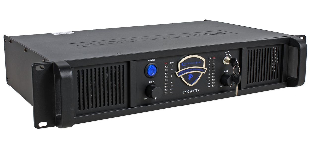
Image: Front view of the Technical Pro LZ6200 amplifier, displaying the power button, level controls, LED meters, and lock switch.
- POWER Button: Toggles the amplifier's power on and off.
- CH-A / CH-B Level Controls: Rotary knobs to adjust the output level for Channel A and Channel B independently.
- CLIP Indicators: Red LEDs that illuminate when the input signal is too high, indicating potential distortion. Reduce the input level if these LEDs light up frequently.
- LED Meters: Multi-segment LED displays showing the output level for each channel.
- LOCK Switch: A key-operated switch to prevent unauthorized operation of the amplifier. Insert the provided key to enable or disable the amplifier's functions.

Image: Front view of the Technical Pro LZ6200 amplifier with the security key inserted into the lock switch.
5. Rear Panel Connections
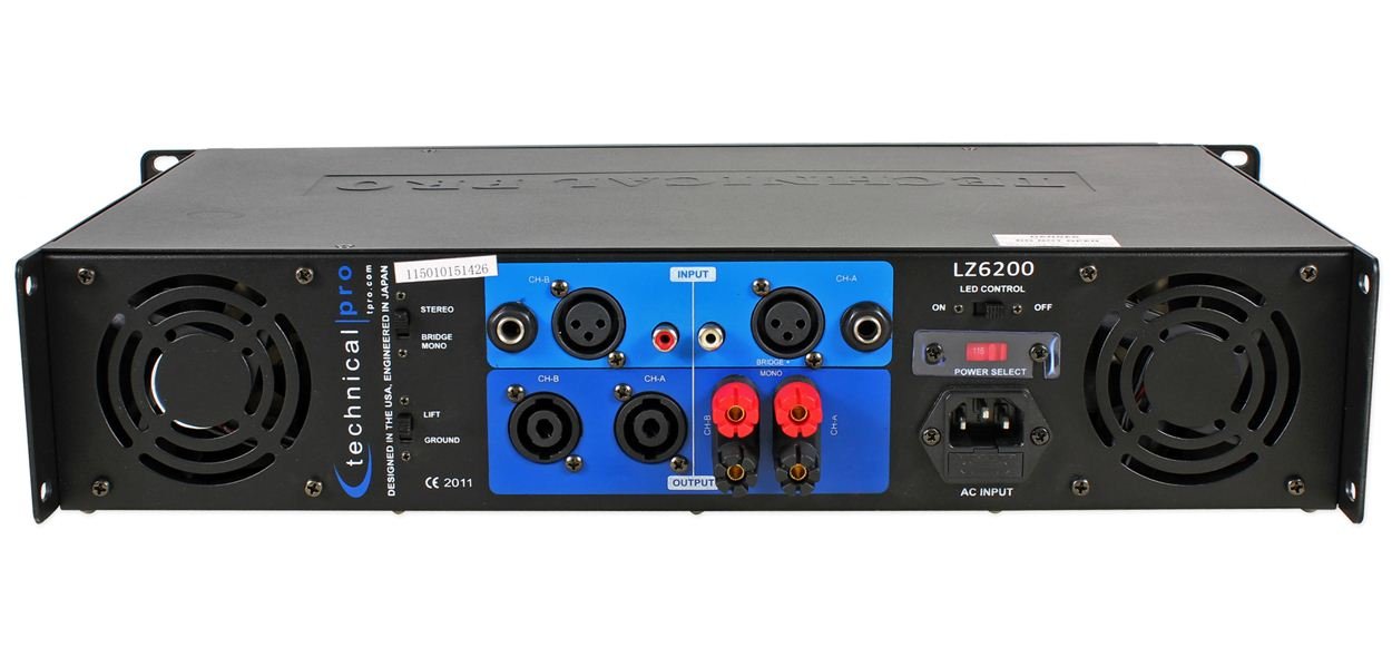
Image: Rear view of the Technical Pro LZ6200 amplifier, showing input and output connectors, mode switches, and power input.
- INPUT (CH-A / CH-B): Balanced XLR and 1/4" TRS combo jacks for connecting audio sources.
- OUTPUT (CH-A / CH-B): Speakon and Binding Post terminals for connecting speakers.
- MODE Switch: Selects the amplifier's operating mode: STEREO (two independent channels), BRIDGE (combines both channels for mono, higher power output), or MONO (parallel input to both channels, independent outputs).
- LIFT / GROUND Switch: Used to break the ground loop if hum or noise is present in the audio signal.
- LED CONTROL Switch: Toggles the front panel LED meters on or off.
- POWER SELECT Switch (110V/220V): Selects the appropriate operating voltage for your region. Ensure this is set correctly before connecting to power.
- AC INPUT: Standard IEC power inlet for the AC power cable.
6. Setup
6.1 Placement
Position the amplifier in a location that allows for proper ventilation. Avoid enclosed spaces or stacking other heat-generating equipment directly on top of the unit. Ensure the surface is stable and can support the amplifier's weight.
6.2 Power Connection
- Verify the POWER SELECT switch on the rear panel is set to the correct voltage (110V or 220V) for your electrical supply.
- Connect the supplied AC power cable to the AC INPUT on the rear panel and then to a grounded electrical outlet.
6.3 Input Connections
Connect your audio source (mixer, preamplifier, etc.) to the INPUT jacks (XLR or 1/4" TRS) on the rear panel. Use high-quality shielded cables to minimize noise.
6.4 Output Connections (Speakers)
Connect your speakers to the OUTPUT terminals (Speakon or Binding Post) on the rear panel. Ensure correct polarity (+ to + and - to -) for all connections. Match speaker impedance to amplifier capabilities.
6.5 Mode Selection
Set the MODE switch on the rear panel according to your desired configuration:
- STEREO: For typical two-channel operation, with independent signals for Channel A and Channel B.
- BRIDGE: For combining both channels into a single, higher-power mono output. Connect the speaker to the designated bridge output terminals (refer to markings on the unit).
- MONO: For parallel input to both channels, with independent outputs. Both channels receive the same input signal.
7. Operating Instructions
- Ensure all connections (power, input, output) are secure and correct.
- Turn down the CH-A and CH-B Level Controls on the front panel to their minimum (MIN) position.
- Press the POWER button to turn on the amplifier. The power indicator will illuminate.
- If desired, insert the key into the LOCK switch and turn it to the 'ON' position to enable amplifier functions.
- Start playing audio from your source device.
- Slowly increase the CH-A and CH-B Level Controls to achieve the desired volume.
- Monitor the LED Meters to observe output levels and the CLIP Indicators to prevent distortion. If a CLIP indicator flashes frequently, reduce the input level from your source or the amplifier's level control.
- To turn off the amplifier, first reduce the level controls to minimum, then press the POWER button.
8. Maintenance
- Cleaning: Disconnect the amplifier from power before cleaning. Use a soft, dry cloth to wipe the exterior. Do not use liquid cleaners or solvents.
- Ventilation: Regularly check that the ventilation grilles are free from dust and obstructions. Dust accumulation can lead to overheating.
- Connections: Periodically check all cable connections for tightness and wear.
9. Troubleshooting
| Problem | Possible Cause | Solution |
|---|---|---|
| No power | Power cable disconnected; Power switch off; Incorrect voltage selection; Blown fuse; Lock switch engaged. | Check power cable connection; Ensure power switch is ON; Verify 110V/220V switch setting; Check/replace fuse (by qualified personnel); Disengage lock switch with key. |
| No sound output | Input cables disconnected; Speaker cables disconnected/incorrectly wired; Input source not playing; Amplifier level controls at minimum; Incorrect mode selection. | Check all input and output cable connections; Ensure input source is active; Increase amplifier level controls; Verify MODE switch setting. |
| Distorted sound | Input signal too high (clipping); Speaker impedance mismatch; Damaged speaker. | Reduce input level from source or amplifier level controls; Ensure speaker impedance is compatible; Test with different speakers. |
| Hum or noise | Ground loop; Poor cable shielding. | Engage the LIFT switch on the rear panel; Use higher quality shielded cables. |
| Overheating | Blocked ventilation; Excessive load. | Ensure adequate airflow around the unit; Reduce output level or speaker load. |
10. Specifications
- Brand: Technical Pro
- Model: LZ6200
- Channels: 2
- Peak Power: 6200W
- Operating Voltage: 110V/220V (selectable)
- Input Connectors: XLR, 1/4" TRS
- Output Connectors: Speakon, Binding Post
- Surround Sound Channel Configuration: 2
- Dimensions (Package): 52.07 x 35.56 x 14.73 cm (approximately)
- Item Weight: 7.98 kg (approximately)
11. Warranty and Support
For warranty information and technical support, please refer to the documentation provided at the time of purchase or contact Technical Pro customer service directly. Keep your purchase receipt as proof of purchase.
For further assistance, visit the official Technical Pro website or contact their authorized service centers.


