Introduction
The OSD Audio AB12 is an in-wall speaker selector A/B switch designed to manage audio output between two amplifiers and one pair of speakers, or one amplifier and two pairs of speakers. This device allows for convenient selection of audio sources or destinations within a dedicated audio zone. It is rated for up to 100 watts per channel and features a push-button control for easy operation.
Safety Precautions
- Always disconnect power to the amplifier and any connected audio equipment before installation or wiring.
- Ensure all wiring connections are secure to prevent short circuits or damage to equipment.
- Do not exceed the maximum power rating of 100 watts per channel.
- Consult a qualified electrician if you are unsure about any electrical wiring procedures.
Setup and Installation
Tools Required
- Screwdriver (Phillips head)
- Wire strippers
- Electrical tape (optional)
- Standard single-gang junction box (if not already installed)
Wiring Instructions
The AB12 features removable, solderless terminals for easy wiring. It accepts speaker wire up to 14 gauge. For optimal sound quality, 14-16 gauge wire is recommended.
- Prepare Wires: Strip approximately 1/4 to 1/2 inch of insulation from the ends of your speaker wires. Twist the bare wire strands tightly.
- Identify Terminals: The AB12 has clearly labeled terminals for 'OUTPUT' (to speakers) and 'AMP A INPUT' / 'AMP B INPUT' (from amplifiers). Each input/output has terminals for Left (+) and (-), and Right (+) and (-).
- Connect Speakers: Connect your speaker wires to the 'OUTPUT' terminals. Ensure correct polarity (positive to positive, negative to negative).
- Connect Amplifiers: Connect the speaker output wires from your primary amplifier to the 'AMP A INPUT' terminals. Connect the speaker output wires from your secondary amplifier (if used) to the 'AMP B INPUT' terminals. Maintain correct polarity.
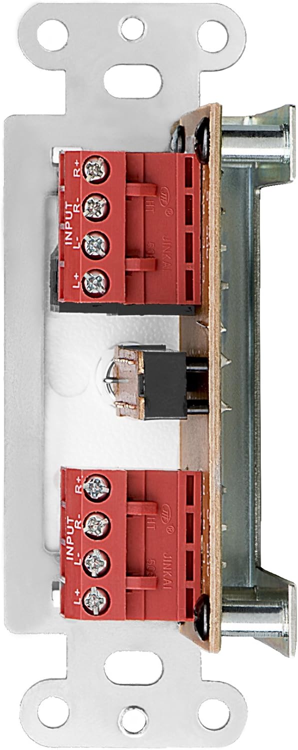
Figure 1: Rear view of the AB12 switch with clearly labeled input and output terminals for wiring.

Figure 2: Example of speaker wire connections to the removable solderless terminals.
Mounting the Switch
The AB12 is designed to fit into a standard single-gang junction box with a minimum depth of 2.9 inches. The dimensions of the selector are approximately 1 inch (W) x 2.75 inches (H) x 1.75 inches (D).
- Prepare Junction Box: Ensure the junction box is securely installed in the wall.
- Insert Switch: Carefully push the wired AB12 switch into the junction box. Ensure wires are not pinched.
- Secure Faceplate: Attach the desired color faceplate (white, beige, or light almond options are typically included) over the switch and secure it to the junction box using the provided screws.

Figure 3: Mounting brackets for securing the switch within a standard gang box.
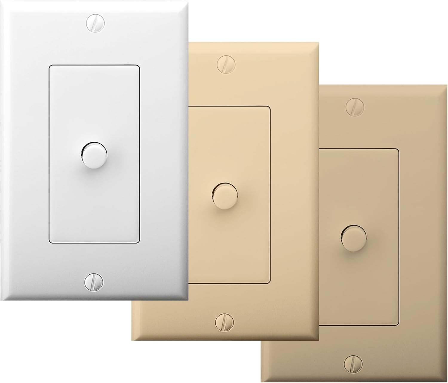
Figure 4: The AB12 switch typically includes multiple faceplate colors for aesthetic integration.
Operating Instructions
The OSD Audio AB12 switch provides a simple push-button mechanism to select between two audio configurations.
Functionality
- Two Amplifiers to One Speaker Pair: Connect two amplifiers to 'AMP A INPUT' and 'AMP B INPUT' respectively. Connect one pair of speakers to 'OUTPUT'. Press the button to switch between Amplifier A and Amplifier B playing through the single speaker pair.
- One Amplifier to Two Speaker Pairs: Connect one amplifier to 'AMP A INPUT'. Connect two pairs of speakers to 'OUTPUT' (one pair wired to the 'A' side of the output terminals, the other to the 'B' side, if applicable, or use the switch to select between two distinct output paths). Press the button to switch between Speaker Pair A and Speaker Pair B playing from the single amplifier.
The switch is designed to allow power to flow to speakers from either A or B, but not from both simultaneously. This prevents potential damage to amplifiers or speakers due to conflicting signals.

Figure 5: The AB12 switch integrated into an audio system, allowing selection between different sources or destinations.
Maintenance
The OSD Audio AB12 In-Wall Speaker Selector requires minimal maintenance.
- Cleaning: To clean the faceplate, gently wipe it with a soft, dry cloth. Avoid using abrasive cleaners or solvents, as these can damage the finish.
- Connections: Periodically check all wiring connections to ensure they remain secure. Loose connections can lead to signal loss or poor audio quality.
- Environment: Ensure the switch is installed in a dry environment, away from excessive heat or moisture.
Troubleshooting
If you encounter issues with your AB12 speaker selector, refer to the following troubleshooting steps:
| Problem | Possible Cause | Solution |
|---|---|---|
| No sound from speakers | Loose wiring connections Incorrect switch position Amplifier or speaker issue | Check all speaker wire connections at the AB12 switch and at the amplifier/speakers. Ensure the switch is fully engaged in the desired A or B position. Verify amplifier and speakers are functioning correctly by bypassing the switch temporarily. |
| Sound from only one speaker (left or right channel) | Incorrect wiring polarity Loose connection for one channel Defective switch mechanism | Verify correct positive (+) and negative (-) wiring for both left and right channels. Check connections for the affected channel. If the issue persists, the internal switch mechanism may be faulty; contact support. |
| Difficulty fitting into standard gang box | Insufficient depth or width in junction box Excessive wiring inside box | Ensure the junction box meets the minimum depth requirement (2.9 inches). Carefully arrange wires to minimize bulk. Some older or non-standard boxes may require minor modification (e.g., widening the opening) or a deeper box. |
| Distorted or poor audio quality | Incorrect wire gauge Loose connections Exceeding power rating | Use recommended 14-16 gauge speaker wire. Check all connections. Ensure the amplifier output does not exceed the 100-watt rating of the switch. |
Specifications
| Feature | Specification |
|---|---|
| Model | AB12 |
| Operation Mode | A/B Switch |
| Power Rating | 100 Watts per channel |
| Frequency Response | 20Hz to 20KHz |
| Speaker Wire Gauge | Up to 14 gauge (14-16 gauge recommended) |
| Connector Type | Solderless terminals |
| Actuator Type | Push Button |
| Number of Positions | 2 |
| Mounting Type | Standard Single-Gang Box Mount |
| Product Dimensions (L x W x H) | 4.5 x 2.75 x 2.5 inches |
| Item Weight | 6.4 ounces |
| Material (Housing) | Plastic |
| Contact Material | Metal |
| Color | White (with additional faceplate options) |
Warranty and Support
OSD Audio products are designed for reliability and performance. For warranty information or technical support, please refer to the official OSD Audio website or contact their customer service department. Keep your purchase receipt as proof of purchase for any warranty claims.
Online Support: www.osdaudio.com


