1. Introduction
The Greisinger GIA 2448 is a digital panel meter designed for measuring and visualizing standard signals. This device allows users to select desired measurement ranges via solder bridges, making it versatile for various applications. It supports a wide array of voltage and current inputs, providing clear digital readouts.
This manual provides essential information for the safe and efficient operation of your GIA 2448 panel meter. Please read it thoroughly before installation and use.
2. Safety Information
- Always disconnect power before installation or maintenance.
- Installation and servicing should only be performed by qualified personnel.
- Ensure the device is protected from moisture and extreme temperatures.
- Do not operate the device if it shows signs of damage.
- Observe all local and national electrical safety regulations.
- The device is designed for professional use only.
3. Setup and Installation
The GIA 2448 is an embedded display unit. Proper installation ensures accurate readings and device longevity.
- Panel Cutout: Prepare a panel cutout of 24 x 48 mm for mounting the device.
- Mounting: Insert the GIA 2448 into the prepared cutout and secure it using the provided mounting clips.
- Power Supply: Connect the power supply. The standard voltage supply is 18-29 V/DC, selectable via solder bridge.
- Signal Input: Connect the signal source to the appropriate input terminals.
- Measurement Range Selection: Select the desired measurement range using the solder bridges on the device's circuit board. Refer to the "Operating Instructions" section for available ranges.
- Display Scaling: The display range can be scaled via solder bridges and a potentiometer for customized visualization.
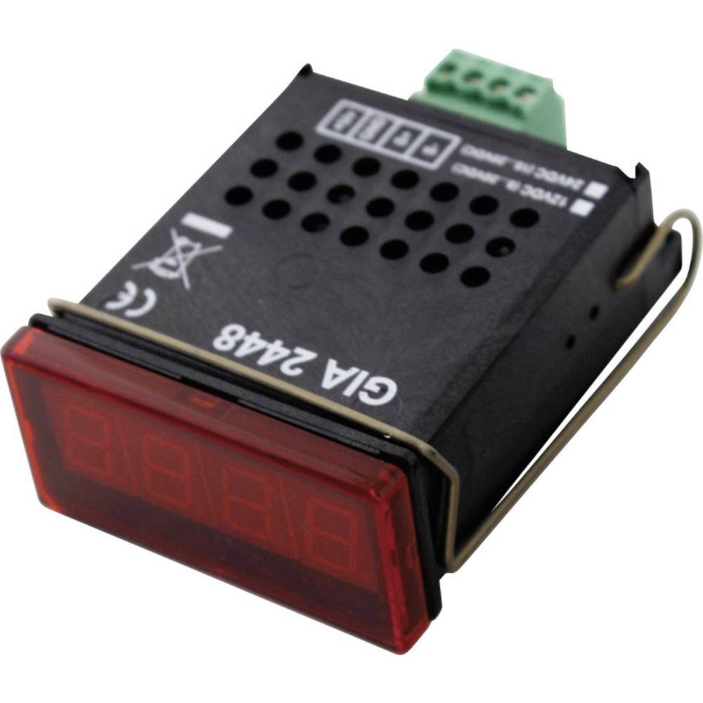
Figure 1: Front view of the Greisinger GIA 2448 Digital Panel Meter. This image shows the compact design and digital display for integration into control panels.
4. Operating Instructions
The GIA 2448 is designed for straightforward operation once installed and configured.
4.1 Measurement Range Selection
The device supports various standard signal measurement ranges. These are selected by configuring specific solder bridges on the internal circuit board. Ensure power is disconnected before making any changes to the solder bridges.
Available measurement functions include:
- 0 - 20 V
- 0 - 10 V
- 0 - 2 V
- 0 - 1 V
- 0 - 200 mV
- 0 - 20 mA
- 4 - 20 mA
Consult the detailed wiring diagram (not provided in this manual, refer to product packaging or manufacturer's website) for the exact location and configuration of the solder bridges for each range.
4.2 Display Reading
Once powered and configured, the GIA 2448 will display the measured signal value on its digital screen. The display is designed for clear readability.
The display field is scalable via solder bridges and a potentiometer, allowing for custom scaling of the input signal to the displayed value.
5. Maintenance
The Greisinger GIA 2448 is designed for low maintenance. Regular cleaning and inspection are recommended.
- Cleaning: Clean the front panel with a soft, damp cloth. Do not use abrasive cleaners or solvents.
- Inspection: Periodically check all connections for tightness and signs of wear or corrosion.
- Calibration: While the device is factory calibrated, professional recalibration may be required periodically depending on application and regulatory requirements.
6. Troubleshooting
| Problem | Possible Cause | Solution |
|---|---|---|
| No display | No power supply or incorrect voltage. | Check power connections and ensure voltage is within 18-29 V/DC. |
| Incorrect reading | Wrong measurement range selected or incorrect scaling. | Verify solder bridge configuration for the correct measurement range. Adjust display scaling potentiometer if necessary. |
| Display shows "OL" or "Err" | Input signal out of selected range. | Select a higher measurement range or check the input signal source. |
7. Specifications
- Model: GIA 2448
- Product Type: Digital Panel Meter
- Dimensions (H x W): 24 mm x 48 mm
- Digit Height: 10 mm
- Protection Class: IP54 (front)
- Measurement Speed: 3 seconds
- Standard Voltage Supply: 18-29 V/DC (selectable via solder bridge)
- Selectable Measurement Ranges:
- Voltage: 0-20 V, 0-10 V, 0-2 V, 0-1 V, 0-200 mV
- Current: 0-20 mA, 4-20 mA
- Display Field: Scalable via solder bridge and potentiometer
8. Warranty and Support
For warranty information and technical support, please refer to the official GREISINGER website or contact your local distributor. Keep your purchase receipt as proof of purchase.
Manufacturer: GREISINGER
Model Number: 600458 (Internal Reference: 102977-62)
ASIN: B005OJU4LC
For further assistance, please visit the GREISINGER official website.


