Introduction
The MFJ-989D Versa Tuner V is a high-power antenna tuner designed for amateur radio use. It facilitates matching a 50-ohm output from an amplifier, transmitter, or transceiver to a wide variety of antennas across the 1.8 to 30 MHz frequency range, including Mars/WARC bands. This tuner is capable of handling up to 1500 watts (CW and SSB) and features a roller inductor 'T' matching network for continuous tuning. A built-in cross-needle meter provides simultaneous display of forward power, reflected power, and SWR.
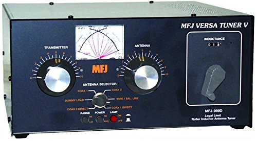
Figure 1: Front panel view of the MFJ-989D Versa Tuner V. This image displays the main controls including the TRANSMITTER and ANTENNA tuning knobs, the INDUCTANCE roller, the cross-needle meter, and the ANTENNA SELECTOR switch. Various smaller switches for RANGE, POWER, and LAMP are also visible.
Features
- Power Handling: Up to 1500 watts (CW and SSB) for amateur legal limit operation.
- Frequency Coverage: Continuous tuning from 1.8 MHz to 30 MHz, including Mars/WARC bands.
- Matching Network: Roller inductor 'T' matching network for precise impedance matching.
- Antenna Compatibility: Matches dipoles, inverted-Vs, verticals, beams, random wires, and other antenna types.
- Metering: Illuminated cross-needle meter displays peak and average forward power, reflected power, and SWR simultaneously.
- Meter Illumination: Powered by a 9-Volt battery or external 12 Vdc/120 Vac with an optional AC adapter.
- Antenna Selector: Six-position switch for selecting various outputs:
- Built-in 300-watt, 50-ohm dummy load.
- Two coaxial line outputs (selectable tuned or direct).
- Single wire line/balanced output.
- Built-in Balun: Supports balanced open wire, twin-lead, or twin-axial feedlines.
Setup
Proper setup is crucial for optimal performance and safety. Ensure all connections are secure before applying power.
- Power Connection: The meter illumination requires power. Install a 9-Volt battery (not included) by removing the top cover (typically secured by screws). Alternatively, connect a 12 Vdc power source or an optional 120 Vac adapter to the designated power input jack on the rear panel.
- Transceiver/Amplifier Connection: Connect the 50-ohm output from your transceiver or amplifier to the 'TRANSMITTER' coaxial connector on the rear panel using a high-quality 50-ohm coaxial cable.
- Antenna Connections:
- Coaxial Antennas: Connect your coaxial fed antennas to the 'COAX 1' and 'COAX 2' connectors on the rear panel.
- Balanced/Single Wire Antennas: For balanced feedlines (e.g., twin-lead, open wire) or single wire antennas, connect them to the appropriate terminals on the rear panel, utilizing the built-in balun.
- Grounding: Connect the tuner to a good station ground using the ground terminal on the rear panel. This is essential for safety and performance.
Operating Instructions
Operating the MFJ-989D involves adjusting the tuning controls to achieve a low Standing Wave Ratio (SWR) for efficient power transfer to the antenna.
- Power On: Ensure the meter illumination is active by pressing the 'LAMP' switch to 'ON' if desired. Select the appropriate power range ('LO' or 'HI') using the 'RANGE' switch.
- Antenna Selection: Set the 'ANTENNA SELECTOR' switch to the desired antenna output. For initial tuning, you might select 'COAX 1 TUNED' or 'WIRE/BAL LINE'.
- Initial Tuning:
- Apply a low power signal (e.g., 5-10 watts) from your transceiver.
- Adjust the 'TRANSMITTER' and 'ANTENNA' tuning knobs, along with the 'INDUCTANCE' roller, to minimize the reflected power and achieve the lowest possible SWR reading on the cross-needle meter.
- The goal is to bring the reflected power needle as close to zero as possible, indicating an SWR of 1:1.
- Fine Tuning: Once a rough match is found, increase power to your desired operating level (within the tuner's limits) and fine-tune the controls for the absolute lowest SWR.
- Dummy Load Use: To test your transceiver or amplifier, set the 'ANTENNA SELECTOR' to 'DUMMY LOAD'. This provides a 50-ohm resistive load. Do not exceed the 300-watt rating of the dummy load for extended periods.
- Direct Coax Operation: The 'COAX 1 DIRECT' and 'COAX 2 DIRECT' positions bypass the tuner's matching network, connecting the transceiver directly to the selected coaxial antenna. Use these positions when your antenna is already resonant at the operating frequency and does not require tuning.
Maintenance
Regular maintenance ensures the longevity and reliable operation of your MFJ-989D tuner.
- Cleaning: Keep the unit clean and free from dust. Use a soft, dry cloth for external cleaning. Avoid liquid cleaners that could seep into the unit.
- Battery Replacement: If the meter illumination dims or fails, replace the 9-Volt battery located inside the unit. Ensure proper polarity when installing the new battery.
- Connection Checks: Periodically inspect all coaxial and wire connections for corrosion or looseness. Ensure all screws securing the chassis are tight.
- Internal Inspection: If you experience unusual operation, a qualified technician may perform an internal inspection. Ensure no wires are loose or interfering with moving parts, particularly around the variable capacitors and roller inductor.
Troubleshooting
This section addresses common issues you might encounter with your MFJ-989D tuner.
- Meter Illumination Not Working:
- Check if the 9-Volt battery is installed correctly and is not depleted.
- Verify external 12 Vdc or 120 Vac power supply connection if used.
- Ensure the 'LAMP' switch is in the 'ON' position.
- Cannot Achieve Low SWR:
- Ensure your antenna system is properly connected and functional.
- Verify the 'ANTENNA SELECTOR' is set to the correct output for your antenna type.
- Confirm the operating frequency is within the tuner's 1.8-30 MHz range.
- Check for faulty coaxial cables or connectors.
- Ensure a good station ground connection.
- Inaccurate Meter Readings:
- Ensure the tuner is properly grounded.
- Verify the 'RANGE' switch is set appropriately for the power level being used.
- If persistent, internal inspection by a qualified technician may be required to check for loose components or calibration issues.
Specifications
| Feature | Specification |
|---|---|
| Model Number | MFJ-989D |
| Frequency Range | 1.8 - 30 MHz |
| Power Handling | 1500 Watts (CW/SSB) |
| Matching Network | Roller Inductor 'T' Network |
| Antenna Outputs | 2 Coaxial, 1 Wire/Balanced Line, 1 Dummy Load |
| Dummy Load | Built-in 300 Watt, 50 Ohm |
| Meter Illumination | 9V Battery or 12V DC / 120V AC (optional adapter) |
| Product Dimensions | 17 x 17 x 11 inches |
| Item Weight | 11.62 pounds |
| Color | Black |
| UPC | 702685258973 |
Warranty and Support
MFJ Enterprises, Inc. typically provides a 1-year limited warranty on their products, covering defects in materials and workmanship. For specific warranty details, technical assistance, or repair services, please refer to the official MFJ Enterprises website or contact their customer support directly. Keep your purchase receipt as proof of purchase for warranty claims.
Contact Information: For the most current support options, including contact numbers and service centers, please visit the official MFJ Enterprises website.


