1. Introduction
This manual provides essential information for the proper installation, operation, and maintenance of your Raymarine P66 50/200KHz Transom Mount Transducer. This high-speed transducer is designed to provide depth, speed, and temperature data for compatible echo sounders.
The P66 transducer operates at dual frequencies (50/200 KHz) and is suitable for various hull materials including metal, wood, and fiberglass. For optimal performance and longevity, please follow all instructions carefully.

Figure 1: Front view of the Raymarine P66 Transom Mount Transducer. This image shows the main body of the transducer, designed for mounting on a boat's transom.
2. Product Features
The Raymarine P66 Transom Mount Transducer offers the following key features:
- Dual Frequency Operation: Provides 50 KHz and 200 KHz frequencies for versatile depth sounding.
- Multi-Sensor Capability: Integrates depth, speed, and temperature sensing into a single unit.
- High Power Output: Rated for a maximum power of 600 Watts.
- Wide Beam Angles: Features a 45° beam angle at 50 KHz and an 11° beam angle at 200 KHz.
- Durable Cable: Equipped with a 30-foot (10-meter) cable for flexible installation.
- Replaceable Paddle Wheel: Includes a replaceable paddle wheel assembly for speed sensing.
- Broad Compatibility: Compatible with various Raymarine echo sounders and suitable for metal, wood, and fiberglass hulls.
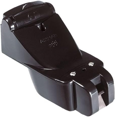
Figure 2: Side view of the Raymarine P66 Transom Mount Transducer, showing its profile and mounting bracket.
3. Compatibility
The P66 Transom Mount Transducer is compatible with the following Raymarine Echo Sounders:
- SL Series: SL755RC, SL760RC, SL1250, SL1250RC
- hsb2 Plus Series: L755RC, L760, L760RC, L1250, L1250RC
- hsb2 HDFI Series: DSM250, L770D, L770DRC, L1260D, L1260DRC
Note:
- An E66066 adapter cable is required for connection to Raymarine a, c, e, and eS Series displays.
- Compatible hull materials include metal, wood, and fiberglass.
4. Setup and Installation
Proper installation is crucial for the accurate performance of your transducer. It is recommended that installation be performed by a qualified marine technician.
4.1 Choosing a Mounting Location
Select a location on the transom that is:
- Free from turbulence caused by the hull, propeller, or other transducers.
- Accessible for maintenance and adjustment.
- Below the waterline at all speeds.
4.2 Mounting the Transducer
- Position the transducer bracket on the transom, ensuring the transducer face is parallel to the waterline.
- Mark and drill pilot holes for the mounting screws.
- Secure the bracket to the transom using appropriate marine-grade fasteners and sealant to prevent water intrusion.
- Attach the transducer to the bracket, allowing for adjustment of the angle.
- Route the transducer cable away from sources of electrical interference and sharp edges, securing it with cable clamps.
4.3 Electrical Connection
Connect the transducer cable to your compatible Raymarine echo sounder or display unit. If connecting to a, c, e, or eS Series displays, ensure the E66066 adapter cable is used as an intermediary.
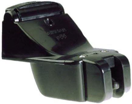
Figure 3: Bottom view of the Raymarine P66 Transom Mount Transducer, showing the paddle wheel and sensor elements.
5. Operating Instructions
Once installed and connected, the P66 transducer will transmit data to your compatible Raymarine display. Refer to your echo sounder's manual for specific operating procedures.
5.1 Depth Readings
The transducer emits sound waves and measures the time it takes for the echo to return, calculating depth. Ensure your display is set to the correct frequency (50 KHz for deeper water penetration, 200 KHz for higher detail in shallower water).
5.2 Speed Readings
The paddle wheel rotates as water flows past it, generating pulses that are converted into speed data. Ensure the paddle wheel is free from obstructions for accurate readings.
5.3 Temperature Readings
An integrated sensor provides water temperature data, which is displayed on your connected unit.

Figure 4: Diagram illustrating the transducer's sonar beam. This image visually represents how the transducer emits and receives sonar signals to detect underwater objects and depth.
6. Maintenance
Regular maintenance ensures the continued accuracy and performance of your transducer.
- Cleaning: Periodically inspect the transducer face and paddle wheel for marine growth, dirt, or debris. Clean gently with a soft cloth and mild soap. Avoid abrasive cleaners or tools that could scratch the surface.
- Paddle Wheel Inspection: Check the paddle wheel for free rotation. If it is stiff or damaged, it can be replaced. Refer to the manufacturer's instructions for paddle wheel replacement.
- Cable Inspection: Inspect the cable for any signs of wear, cuts, or damage. Ensure all connections are secure and free from corrosion.
7. Troubleshooting
If you experience issues with your transducer, consider the following common troubleshooting steps:
- No Depth/Speed/Temperature Reading:
- Verify all cable connections are secure and free from corrosion.
- Ensure the transducer is properly submerged and free from air bubbles or turbulence.
- Check the settings on your echo sounder to ensure the transducer is recognized and configured correctly.
- Inspect the transducer face for fouling or damage.
- Inaccurate Speed Reading:
- Clean the paddle wheel and ensure it rotates freely.
- Check for obstructions around the paddle wheel.
- Verify the paddle wheel is correctly installed and not damaged.
- Intermittent Readings:
- Examine the cable for kinks, cuts, or damage.
- Ensure the transducer is not experiencing excessive turbulence from the hull or propeller.
- Check for electrical interference from other onboard electronics.
If problems persist, consult your Raymarine echo sounder's manual or contact Raymarine customer support.
8. Specifications
| Model | P66 Transom Mount Transducer |
| Part Number | A80170 (or equivalent for 50/200KHz S/T, Trnsm Mnt Xdcr, DSM30/300) |
| Max Power | 600 W |
| Frequency | 50/200 kHz |
| Beam Angles | 200 kHz: 11°, 50 kHz: 45° |
| Cable Length | 30 ft (10 m) |
| Mounting Type | Transom Mount |
| Functions | Depth, Speed, Temperature |
| Compatible Hull Material | Metal, Wood, Fiberglass |
| Item Weight | 6.17 pounds (2.8 kg) |
| Product Dimensions | 10 x 7 x 4 inches (25.4 x 17.8 x 10.2 cm) |
9. Warranty and Support
For detailed warranty information and technical support, please refer to the official Raymarine website or contact your authorized Raymarine dealer. Keep your proof of purchase for warranty claims.
Raymarine Website: www.raymarine.com


