1. Introduction
The Intermatic T101P ON/Off T100 Series Mechanical Timer Switch is a dependable device designed to control electrical loads up to 40 Amperes. It allows for scheduled ON/OFF operations over a 24-hour period, offering convenience and energy management for various applications. This manual provides essential information for the safe installation, operation, and maintenance of your timer switch.
2. Safety Information
Please read and understand all instructions before installing or operating this device. Failure to follow these instructions may result in electrical shock, fire, or serious injury.
- WARNING: Disconnect power at the main circuit breaker or fuse box before installing or servicing the timer switch.
- Installation should be performed by a qualified electrician in accordance with all national and local electrical codes.
- Do not connect aluminum wires directly to the switch terminals. Use appropriate copper-to-aluminum connectors if necessary.
- Ensure the timer switch is installed in a suitable NEMA 3R enclosure for outdoor or damp locations.
- Verify that the voltage and current ratings of the timer switch match your application requirements.
3. Package Contents
Verify that all components are present before beginning installation:
- Intermatic T101P Mechanical Timer Switch
- Instruction Manual (this document)
- Mounting hardware (if included with specific packaging)
4. Product Features
- 24-Hour Operation: Provides up to 12 ON/OFF operations per day.
- High Capacity: Handles electrical loads up to 40 Amperes per pole.
- Manual Override: Features a convenient manual lever for temporary ON/OFF control without affecting programmed settings.
- Durable Enclosure: NEMA 3R rated plastic enclosure suitable for indoor and outdoor use.
- Versatile Applications: Ideal for lighting, signs, filters, electric fences, fans, conveyors, pool heaters, blowers, and pumps.
5. Installation
Follow these steps for proper installation of the Intermatic T101P timer switch:
- Power Disconnection: Turn OFF power at the main service panel before beginning any wiring. Ensure the circuit is de-energized using a voltage tester.
- Mounting: Select a suitable location for the timer switch. Mount the enclosure securely using appropriate screws and anchors.
- Wiring: Refer to the wiring diagram inside the timer switch enclosure and the image below. Connect the incoming power (LINE) and outgoing load (LOAD) wires to the designated terminals.

Figure 1: Internal view of the Intermatic T101P timer switch, showing the dial, manual lever, and wiring terminals. Note the 'OFF' and 'ON' positions for the manual lever, and the 'LINE' and 'LOAD' connections.
- Important Wiring Notes:
- Observe the warning: DO NOT REMOVE THIS INSULATOR. This component is crucial for safety and proper operation. Wire, lift, and swing the insulator as needed, then replace it after wiring.
- DO NOT CONNECT ALUMINUM WIRES TO SWITCH TERMINALS. Use only copper conductors or approved copper-to-aluminum connectors.
- Close Enclosure: Once wiring is complete and verified, securely close the timer switch enclosure.
- Restore Power: Restore power at the main service panel.
6. Operation
The T101P timer switch features a 24-hour dial for setting automatic ON/OFF times and a manual override lever.
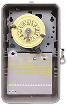
Figure 2: Internal view of the Intermatic T101P timer switch, showing the yellow dial and the protective insulator covering the wiring terminals.
6.1 Setting Automatic ON/OFF Times
- Set Current Time: Rotate the yellow dial clockwise until the current time of day aligns with the time arrow indicator.
- Install ON/OFF Trippers: The timer comes with ON (green) and OFF (red) trippers. Slide these trippers onto the dial at the desired ON and OFF times. Ensure they are securely fastened. The minimum ON/OFF time is 1 hour.
- Verify Operation: The timer will now automatically turn the connected device ON and OFF according to the set schedule.
6.2 Using the Manual Override Lever
The manual override lever allows you to temporarily switch the connected device ON or OFF without disturbing the programmed schedule.
- To manually turn the device ON, push the lever to the 'ON' position.
- To manually turn the device OFF, push the lever to the 'OFF' position.
- The timer will resume its programmed schedule at the next scheduled ON or OFF event.
7. Maintenance
The Intermatic T101P is designed for minimal maintenance. Periodically inspect the unit for any signs of damage or loose connections. Ensure the enclosure is free from debris and moisture. No user-serviceable parts are inside; refer servicing to qualified personnel.
8. Troubleshooting
| Problem | Possible Cause | Solution |
|---|---|---|
| Timer does not operate. | No power to the unit. Incorrect wiring. | Check circuit breaker/fuse. Verify wiring connections are secure and correct. |
| Device does not turn ON/OFF at programmed times. | Trippers incorrectly set. Current time not set correctly. Manual override engaged. | Ensure trippers are firmly in place at desired times. Adjust the dial to the correct current time. Check if the manual override lever is in the neutral position. |
| Timer makes unusual noise. | Internal mechanical issue. | Disconnect power immediately. Contact a qualified electrician or Intermatic customer support. Do not attempt to repair. |
9. Specifications
| Specification | Value |
|---|---|
| Type | 24 Hour Mechanical Timer |
| Maximum Number of Operations | 12 per Day |
| Minimum ON/OFF Time | 1 Hour |
| Switch Type | SPST (Single Pole Single Throw) |
| Current Rating (Resistive/Inductive/Tungsten) | 40 Amp |
| Current Rating (Ballast) | 16 Amp at 277 Volt AC |
| Current Rating (Motor, Full Load) | 24 Amp at 120 Volt AC, 28 Amp at 240 Volt AC |
| Voltage Rating | 120 Volt AC at 60 Hertz |
| Power Rating (Motor) | 2 HP at 120 Volt AC, 5 HP at 240 Volt AC |
| Power Rating (Pilot Duty) | 1000 Volt Amp |
| Power Rating (Input) | 3 Watt |
| Operating Temperature | -40 to 130 Deg F |
| Enclosure | NEMA 3R |
| Material | Plastic |
| Dimensions (W x D x H) | 6.5 Inch x 4 Inch x 10 Inch |
| Color | Beige |
| Item Weight | 1.29 Pounds |
| Approvals | UL (Canada and US), CSA (Canada and US) |
10. Warranty and Support
For warranty information or technical support, please refer to the official Intermatic website or contact their customer service department. Keep your purchase receipt as proof of purchase.


