1. Introduction
This manual provides detailed instructions for the installation, configuration, and operation of the D-Link Xstack DGS-3120-48PC Managed L3 Switch. The DGS-3120-48PC is a high-performance Layer 3 managed switch designed for enterprise and campus networks, offering advanced features for network management, security, and quality of service.
2. Key Features
- 44 x 10/100/1000BASE-T PoE Ports: Provides power and data over a single Ethernet cable to connected devices.
- 4 x Combo SFP Ports: Offers flexible uplink options using fiber or copper transceivers.
- Layer 3 Management: Supports static routing for efficient network segmentation and traffic management.
- Advanced QoS: Prioritizes network traffic to ensure optimal performance for critical applications.
- Robust Security Features: Includes access control lists (ACLs), port security, and authentication mechanisms.
- Standard and Enhanced Software Images: Offers different feature sets (SI for basic L2/L3, EI for advanced L3 features like ERPS, Double VLAN, IPv6).
3. Package Contents
Verify the following items are included in your DGS-3120-48PC package:
- D-Link DGS-3120-48PC Switch
- Power Cord
- Rack Mount Kit (brackets and screws)
- Console Cable (RJ-45 to DB-9)
- Rubber Feet (for desktop installation)
- Quick Installation Guide
If any item is missing or damaged, please contact your local D-Link reseller for assistance.
4. Physical Description
4.1. Front Panel
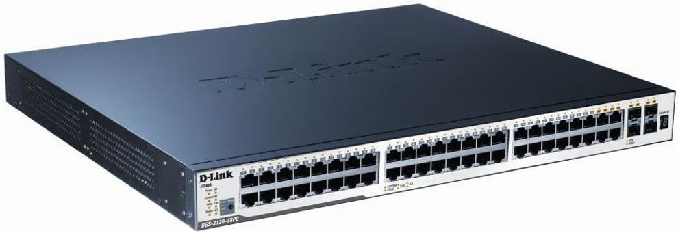
Figure 1: D-Link DGS-3120-48PC Front Panel
The front panel of the DGS-3120-48PC switch features 44 Gigabit Ethernet ports with Power over Ethernet (PoE) capabilities, and 4 additional combo SFP ports for flexible uplink connections. LED indicators provide status information for power, system, and individual port activity.
LED Indicators:
- Power LED: Indicates power status (On/Off).
- System LED: Indicates system operational status.
- Link/Act/Speed LEDs (per port): Indicates link status, activity, and connection speed (10/100/1000 Mbps).
- PoE Status LEDs (per PoE port): Indicates PoE power delivery status.
Ports:
- RJ-45 Ports (1-44): 10/100/1000BASE-T Gigabit Ethernet ports with PoE.
- Combo SFP Ports (45-48): Can be used with SFP transceivers for fiber connections or with corresponding RJ-45 ports for copper connections.
- Console Port: RJ-45 port for command-line interface (CLI) management.
4.2. Rear Panel
The rear panel typically includes the AC power inlet, grounding screw, and possibly ventilation openings. Specific details may vary slightly.
- AC Power Inlet: Connects to the power cord.
- Grounding Screw: For connecting an earth ground cable.
5. Setup and Installation
5.1. Safety Precautions
- Ensure the power supply voltage matches the switch's requirements.
- Do not block ventilation openings.
- Avoid placing the switch in direct sunlight, near heat sources, or in areas with high humidity.
- Ensure proper grounding to prevent electrical hazards.
5.2. Mounting the Switch
Desktop Installation:
- Attach the included rubber feet to the bottom of the switch.
- Place the switch on a flat, stable surface with adequate ventilation.
Rack Installation:
- Attach the two rack-mounting brackets to the sides of the switch using the provided screws.
- Secure the switch in a standard 19-inch equipment rack using appropriate rack screws.
5.3. Connecting Power
- Connect one end of the AC power cord to the power inlet on the rear panel of the switch.
- Connect the other end of the power cord to a grounded electrical outlet.
- Ensure the Power LED on the front panel illuminates, indicating the switch is receiving power.
5.4. Connecting Network Devices
- Connect Ethernet cables from your network devices (e.g., computers, servers, access points) to the RJ-45 ports (1-44) on the switch.
- For fiber uplinks, insert compatible SFP transceivers into the SFP ports (45-48) and connect fiber optic cables.
- Observe the Link/Act/Speed LEDs for each connected port to confirm proper connection and activity.
6. Operating the Switch
6.1. Initial Configuration
The DGS-3120-48PC can be configured via a web-based graphical user interface (GUI) or a command-line interface (CLI) through the console port.
Web-based GUI:
- Connect a computer to any of the switch's Ethernet ports.
- Configure your computer's IP address to be in the same subnet as the switch's default IP address (refer to the Quick Installation Guide for default IP).
- Open a web browser and enter the switch's default IP address.
- Log in using the default username and password (refer to documentation).
Command-Line Interface (CLI):
- Connect the console cable from your computer's serial port to the switch's console port.
- Use a terminal emulation program (e.g., PuTTY, Tera Term) with appropriate serial port settings (e.g., 115200 baud, 8 data bits, no parity, 1 stop bit, no flow control).
- Log in using the default username and password.
6.2. Basic Network Configuration
After initial access, it is recommended to:
- Change the default administrator password.
- Configure the switch's IP address, subnet mask, and default gateway.
- Set up system time and NTP synchronization.
6.3. Advanced Features
The DGS-3120-48PC supports a wide range of advanced features:
- VLANs (Virtual Local Area Networks): Segment your network for improved security and performance.
- Spanning Tree Protocol (STP/RSTP/MSTP): Prevents network loops.
- Link Aggregation (LACP): Increases bandwidth and provides link redundancy.
- Quality of Service (QoS): Prioritizes traffic based on various criteria.
- Access Control Lists (ACLs): Filters network traffic based on defined rules.
- PoE Management: Control power delivery to connected PoE devices.
- Static Routing: Configure routes for inter-VLAN or inter-network communication.
Refer to the D-Link DGS-3120 Series User Manual for detailed configuration instructions on these advanced features.
7. Maintenance
7.1. Firmware Updates
Regularly check the D-Link support website for the latest firmware versions. Firmware updates can provide new features, performance improvements, and security patches. Follow the instructions provided with the firmware download carefully.
7.2. Cleaning
To maintain optimal performance and extend the lifespan of your switch:
- Ensure the switch is powered off and unplugged before cleaning.
- Use a soft, dry cloth to wipe the exterior of the switch.
- Use compressed air to clear dust from ventilation openings.
- Do not use liquid or aerosol cleaners.
8. Troubleshooting
This section provides solutions to common issues you may encounter with the DGS-3120-48PC switch.
| Problem | Possible Cause | Solution |
|---|---|---|
| No Power LED indication | Power cord not connected; Power outlet faulty; Switch power supply issue. | Ensure power cord is securely connected. Test power outlet with another device. Contact D-Link support if issue persists. |
| No Link/Act LED on connected port | Incorrect cable type; Faulty cable; Connected device is off or faulty; Port configuration issue. | Use appropriate Ethernet cable (Cat5e/6). Replace cable. Ensure connected device is powered on and functioning. Check port status in switch management interface. |
| Cannot access web GUI | Incorrect IP address configuration on PC; Switch IP address changed; Network connectivity issue. | Verify PC's IP address is in the same subnet as the switch. Try accessing via console CLI. Check network cable connection. |
| PoE device not receiving power | PoE budget exceeded; Device not PoE compatible; Cable issue; PoE port disabled. | Check PoE budget in switch management. Ensure device is 802.3af/at compliant. Verify cable integrity. Enable PoE on the port if disabled. |
9. Specifications
| Feature | Description |
|---|---|
| Model | DGS-3120-48PC |
| Brand | D-Link |
| Ports | 44 x 10/100/1000BASE-T PoE, 4 x Combo SFP |
| Interface Type | PoE, SFP |
| Data Transfer Rate | 1 Gigabits Per Second (per port) |
| Layer Support | Layer 3 Managed |
| Product Dimensions | 14.96 x 17.32 x 1.73 inches (38 x 44 x 4.4 cm) |
| Item Weight | 19.98 pounds (9.08 Kilograms) |
| UPC | 790069344510 |
| First Available | August 8, 2012 |
10. Warranty and Technical Support
For information regarding the warranty policy, please refer to the warranty card included with your product or visit the official D-Link website. Technical support resources, including FAQs, documentation, and software downloads, are available on the D-Link support portal. Please have your product model and serial number ready when contacting support.
D-Link Website: www.dlink.com


