1. Introduction
Thank you for purchasing the Kaise SK-7722 AC/DC Digital Clamp Meter. This instrument is designed for precise and versatile electrical measurements, featuring a unique 2-channel dual display capability. It allows for simultaneous measurement of two electrical parameters, such as DC current and DC voltage, or AC voltage and frequency, providing comprehensive data at a glance. The SK-7722 is an essential tool for professionals working with automotive electrical systems, including modern electric and hybrid vehicles, as well as general electrical equipment.
Its robust design includes dust and splash-proof features, ensuring reliability in various working environments. With capabilities for measuring AC/DC current up to 1000A, AC/DC voltage, resistance, frequency, duty cycle, and pulse width, this meter offers extensive functionality. An analog output terminal further enhances its utility by allowing connection to external recorders or oscilloscopes for detailed data logging and waveform analysis.
2. Safety Information
To ensure safe operation and to avoid damage to the meter, please read and understand all safety instructions before use. Always adhere to local and national safety codes.
- Do not exceed the maximum input limits for any function. Refer to the specifications section for details.
- Use caution when working with voltages above 30V AC RMS, 42V peak, or 60V DC. These voltages pose a shock hazard.
- Inspect test leads for damaged insulation or exposed metal. Replace if damaged.
- Ensure the function switch is in the correct position before making any measurement.
- Do not use the meter if it appears damaged or if it is not operating properly.
- Keep fingers behind the finger guards on the test probes during measurements.
- Remove test leads from the circuit before changing functions.
- Replace batteries immediately when the low battery indicator appears to ensure accurate readings.
3. Product Overview
The Kaise SK-7722 is a compact and feature-rich digital clamp meter designed for ease of use and accuracy.
3.1 Components

Figure 1: Kaise SK-7722 Digital Clamp Meter, including test leads, a 9V battery, and a protective carrying case.
3.2 Controls and Display
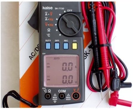
Figure 2: Detailed view of the SK-7722's dual LCD display, rotary function dial, and control buttons.
- Clamp Jaws: Used for non-contact AC/DC current measurement.
- Function Rotary Dial: Selects the desired measurement function (e.g., A~, V~, V-, Ω, Hz, etc.).
- Dual LCD Display: Shows two measurement readings simultaneously (e.g., current and voltage, or voltage and frequency). Features a 4000-count resolution.
- DUTY Button: Activates duty cycle measurement.
- DIFF Button: Used for differential measurements (if applicable).
- REC Button: Activates data recording mode.
- DH Button: Data Hold function, freezes the current display reading.
- Input Terminals (VΩHz, COM, CH2): Connect test leads for voltage, resistance, frequency, and other measurements.
- Analog Output Terminal: For connecting to external recording devices or oscilloscopes.
4. Setup
4.1 Battery Installation
- Ensure the meter is turned OFF.
- Locate the battery compartment cover on the rear of the meter.
- Use a screwdriver to loosen the screw(s) and remove the cover.
- Insert a new 9V battery, observing the correct polarity (+ and -).
- Replace the battery compartment cover and secure it with the screw(s).
4.2 Connecting Test Leads
- For voltage, resistance, and frequency measurements, insert the black test lead into the COM terminal.
- Insert the red test lead into the VΩHz terminal.
- For specific 2-channel measurements or other functions requiring a second input, refer to the operating instructions for connecting to the CH2 terminal.
- Ensure connections are secure before proceeding with measurements.
5. Operating Instructions
5.1 General Measurement Procedure
- Turn the rotary dial to the desired measurement function.
- Connect the test leads or clamp the jaws to the circuit under test as appropriate for the selected function.
- Read the measurement value(s) on the dual LCD display.
- If the reading is unstable or out of range, adjust the function or range if manual ranging is available.
5.2 AC/DC Current Measurement (Clamp)
This function measures current without breaking the circuit.
- Turn the rotary dial to the A~ (AC Current) or A- (DC Current) position.
- Open the clamp jaws by pressing the trigger.
- Enclose only one conductor of the circuit within the jaws. Ensure the jaws are fully closed.
- Read the current value on the display. For DC current, observe the polarity.
5.3 AC/DC Voltage Measurement
- Connect the black test lead to the COM terminal and the red test lead to the VΩHz terminal.
- Turn the rotary dial to the V~ (AC Voltage) or V- (DC Voltage) position.
- Touch the test probes to the desired test points in the circuit.
- Read the voltage value on the display.
5.4 Resistance Measurement and Continuity Test
- Ensure the circuit under test is de-energized.
- Connect the black test lead to the COM terminal and the red test lead to the VΩHz terminal.
- Turn the rotary dial to the Ω (Resistance) position.
- Touch the test probes across the component or circuit section to be measured.
- For continuity, if the resistance is below a certain threshold (typically <50Ω), the meter will emit an audible beep.
5.5 Frequency, Duty Cycle, and Pulse Width Measurement
These functions are particularly useful for automotive diagnostics and signal analysis.
- Connect the test leads as for voltage measurement (COM and VΩHz).
- Turn the rotary dial to the Hz position.
- Touch the test probes to the signal source. The display will show the frequency.
- Press the DUTY button to switch to duty cycle measurement.
- The meter may also provide pulse width measurement in this mode or a related function.
5.6 Special Functions
- MAX/MIN/PEAK Measurement: The meter can capture and display the maximum, minimum, or peak values during a measurement session. Refer to the specific button (often labeled MAX/MIN or PEAK) and follow on-screen prompts.
- Display Hold (DH): Press the DH button to freeze the current reading on the display. Press again to release.
- Analog Output: The analog output terminal provides a voltage signal proportional to the measured value. This allows connection to oscilloscopes or data recorders for detailed waveform analysis or long-term data logging. Consult the meter's specific output ratio for accurate interpretation.
- 2-Channel Dual Display: The SK-7722 can display two different parameters simultaneously. For example, when measuring DC current with the clamp, you might also measure DC voltage using the test leads, with both values appearing on the upper and lower segments of the LCD.
6. Maintenance
6.1 Cleaning
Wipe the meter with a damp cloth and a mild detergent. Do not use abrasives or solvents. Ensure the meter is dry before storage or use.
6.2 Battery Replacement
Replace the 9V battery as described in Section 4.1 when the low battery indicator appears on the display. Remove the battery if the meter is not to be used for an extended period.
6.3 Storage
Store the meter in a cool, dry place, away from direct sunlight and extreme temperatures. Use the provided carrying case for protection.
7. Troubleshooting
If the meter does not function properly, check the following common issues before seeking service.
| Problem | Possible Cause | Solution |
|---|---|---|
| No display or faint display | Dead or weak battery | Replace the 9V battery. |
| Incorrect readings | Incorrect function selected, poor test lead connection, or exceeding input limits. | Verify function dial position, ensure secure test lead connections, and check input limits. |
| "OL" or "OVER" displayed | Measurement exceeds the selected range. | Select a higher range or a different measurement function. |
| Meter does not respond | Internal fault or severe overload. | Turn off the meter, remove batteries, wait a few minutes, then reinsert and restart. If the problem persists, contact support. |
8. Specifications
The following specifications are typical unless otherwise stated.
| Measurement Function | Range | Details |
|---|---|---|
| AC/DC Current | 400A / 1000A | Via clamp jaws |
| AC/DC Voltage | 40V / 250V | Via test leads |
| Resistance | 4KΩ / 20KΩ | Via test leads |
| Display Count | 4000 counts | Dual LCD display |
| Dimensions (H x W x D) | 200 x 64 x 33 mm | Approximate |
| Special Features | Max/Min Peak Measurement, Display Hold, Dust/Splash Proof, Analog Output, Frequency, Duty Cycle, Pulse Width |
9. Warranty and Support
Kaise products are manufactured to high standards and are warranted against defects in materials and workmanship. For specific warranty terms and conditions, please refer to the warranty card included with your product or contact your local Kaise distributor or customer service.
For technical support, troubleshooting assistance, or service inquiries, please contact Kaise customer support through their official website or the contact information provided with your purchase. Please have your model number (SK-7722) and purchase details ready when contacting support.


