1. Introduction
This manual provides detailed instructions for the installation, operation, and maintenance of the Eaton Accell AIM06-A-K Smart Dimmer. This device is designed for smooth, full-range digital dimming of incandescent, magnetic low-voltage, and fluorescent lighting. Please read these instructions carefully before installation and use.
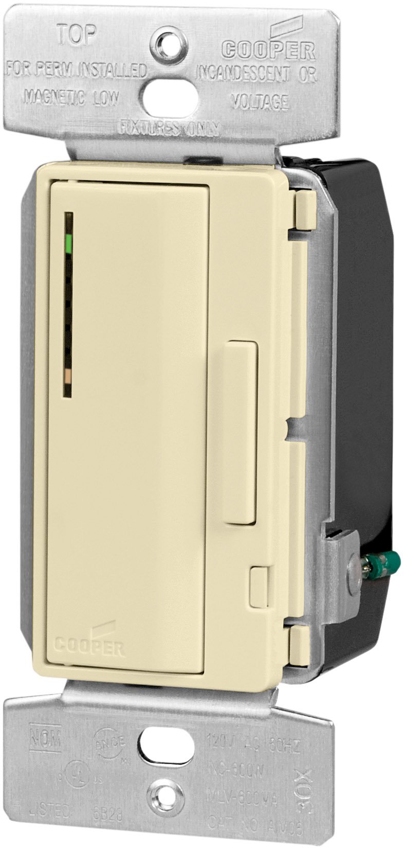
Image 1.1: Eaton Accell AIM06-A-K Smart Dimmer in Almond. This image shows the front view of the dimmer switch, highlighting its push pad and dim/bright bar.
2. Safety Information
WARNING: To avoid fire, shock, or death, turn off power at the circuit breaker or fuse box and test that power is off before wiring.
- Installation must be performed by a qualified electrician in accordance with all local and national electrical codes.
- Do not use with loads exceeding 600 Watts for incandescent/halogen or magnetic low-voltage lighting.
- Ensure all wire connections are secure.
- This device is for indoor use only.
- Do not attempt to repair or modify the device. Refer servicing to qualified personnel.
3. Package Contents
Verify that all components are present before beginning installation:
- Eaton Accell AIM06-A-K Smart Dimmer (Almond)
- Wire Nuts (typically included for connections)
- Instruction Manual (this document)
4. Key Features
- Single-pole and multi-location smart dimmer functionality.
- Smooth, full-range digital dimming for incandescent, magnetic low-voltage, and fluorescent lighting.
- Electro-mechanical push pad for ON/OFF operation with a separate dim/bright bar.
- Preset feature allows return to the previous light setting.
- LED light level display for presetting illumination levels.
- Amber LED at the bottom indicates ON/OFF load status.
- Seven-step green LED display indicates selected light level and reduces brightness when off (night light feature).
- Digital circuitry provides soft-on/fade-off, extending lamp life.
- Neutral wire is not required for installation.
- Compatible with any decorator designer-style wallplates.
5. Installation
- Turn Off Power: At the circuit breaker or fuse box, turn off the power to the switch location. Verify power is off using a voltage tester.
- Remove Old Switch: Carefully remove the existing wallplate and switch from the wall box. Disconnect the wires from the old switch.
- Identify Wires:
- Line Wire: The wire bringing power from the circuit breaker.
- Load Wire: The wire going to the light fixture.
- Ground Wire: Bare copper or green insulated wire.
- Traveler Wires (for multi-location): If replacing a 3-way or 4-way switch, identify the traveler wires.
- Wire the Dimmer: Connect the wires to the dimmer according to the wiring diagram provided with the product.
- Connect the Line wire to the dimmer's Line terminal.
- Connect the Load wire to the dimmer's Load terminal.
- Connect the Ground wire to the dimmer's Ground terminal.
- For multi-location installations, connect traveler wires as per the specific diagram for your setup.
Note: The AIM06-A-K dimmer does not require a neutral wire for installation.
- Mount the Dimmer: Carefully fold the wires into the wall box and secure the dimmer to the wall box using the provided screws.
- Install Wallplate: Attach a decorator-style wallplate (sold separately) over the dimmer.
- Restore Power: Turn the power back on at the circuit breaker.
- Test Operation: Test the dimmer's ON/OFF function and dimming capabilities.
6. Operation
- Turning ON/OFF: Press the large electro-mechanical push pad to turn the lights ON or OFF.
- Dimming/Brightening: Use the separate dim/bright bar located next to the push pad. Press the top of the bar to brighten lights, and the bottom to dim lights.
- Preset Feature: When turning the lights ON, the dimmer will return to the last set brightness level.
- LED Light Level Display: The seven-step green LED display indicates the current light level. When the lights are off, these LEDs reduce brightness, acting as a night light.
- Load Status Indicator: An amber LED at the bottom of the LED display indicates the ON/OFF status of the load.
7. Maintenance
- Cleaning: To clean the dimmer, wipe with a soft, damp cloth. Do not use abrasive cleaners or solvents.
- No User-Serviceable Parts: The dimmer contains no user-serviceable parts. Do not attempt to open or repair the unit.
8. Troubleshooting
| Problem | Possible Cause | Solution |
|---|---|---|
| Lights do not turn ON. |
|
|
| Lights do not dim. |
|
|
| Dimmer is hot to the touch. |
|
|
9. Specifications
- Model: AIM06-A-K
- Brand: Eaton
- Type: Smart Dimmer, Incandescent/Halogen, Magnetic Low-Voltage
- Wattage: 600 Watts (maximum)
- Voltage: 120 Volts AC, 60 Hz
- Operation Mode: Push Button with Dim/Bright Bar
- Color: Almond
- Dimensions (L x W x H): Approximately 2.27 x 2.27 x 2.27 inches (actual faceplate size may vary)
- Certifications: cULus Listed to UL1472, NOM certified
- Connectivity Protocol: X-10
- Neutral Wire: Not required for installation
10. Warranty and Support
For warranty information and technical support, please refer to the official Eaton website or contact Eaton customer service directly. Specific warranty terms may vary by region and purchase date.


