
Introduction
This manual provides comprehensive wiring diagrams and electrical system information for the 2010 Ford Expedition and Navigator models. It is designed for technicians and individuals performing electrical diagnosis and repair, offering detailed schematics, component locations, and testing procedures. This resource is essential for understanding the complex electrical architecture of these vehicles.
Understanding the Manual
Before using the wiring diagrams, familiarize yourself with the manual's structure and conventions. This section explains how to interpret the various symbols, line types, and abbreviations used throughout the diagrams.
- Symbol Legend: Refer to the dedicated section for a complete list of electrical symbols and their meanings.
- Wire Color Codes: Understand the standard color codes used for wiring to correctly identify circuits.
- Connector Views: Diagrams often include pin-out views for connectors, indicating wire locations.
- Component Identification: Each component is labeled with an identifier that corresponds to the component location charts.
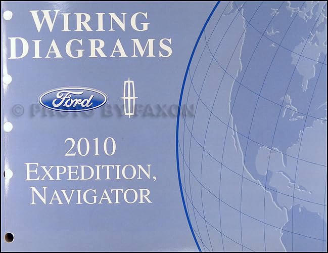
Image: Front cover of the official 2010 Ford Expedition & Navigator Wiring Diagram Manual. This image displays the manual's title and branding, indicating it is a comprehensive guide for vehicle electrical systems.
Operating and Application
This manual is a critical tool for diagnosing and repairing electrical systems. Use the diagrams to trace circuits, identify components, and understand power distribution paths.
- Locate Relevant Diagram: Find the specific system or circuit diagram related to your diagnostic or repair task.
- Identify Components: Use the component location charts and views to physically locate components referenced in the diagrams.
- Trace Circuits: Follow the wire paths through connectors, splices, and components to understand current flow.
- Perform Testing: Utilize the provided testing procedures and specifications to verify component functionality and circuit integrity.
Maintenance and Repair Procedures
The wiring diagrams are indispensable for various maintenance and repair tasks, including:
- Connector Repair: Detailed procedures for repairing damaged connectors and terminals.
- Wiring Harness Overview: Understanding the routing and composition of the vehicle's wiring harnesses.
- Fuse and Relay Information: Comprehensive details on fuse box layouts, relay functions, and power distribution.
- Ground Distribution: Diagrams illustrating the vehicle's grounding points and their connections.
Troubleshooting Electrical Issues
When diagnosing electrical problems, this manual serves as your primary reference. Follow these general steps:
- Symptom Analysis: Understand the reported symptom and identify the affected system.
- Consult Wiring Diagrams: Locate the relevant circuit diagram for the affected system.
- Check Power and Ground: Verify power supply and ground connections to the components in question.
- Test Components: Use the component testing procedures to confirm component functionality.
- Inspect Wiring: Visually inspect wiring for damage, chafing, or corrosion, cross-referencing with the diagrams.
Specifications
| Attribute | Detail |
|---|---|
| Publisher | Ford |
| Publication Date | January 1, 2010 |
| Language | English |
| Item Weight | 2.31 pounds |
| Dimensions | 8.5 x 11 x 1.1 inches |
| ASIN | B0051BXQFY |
Support and Resources
For additional technical support or official Ford service information, please refer to authorized Ford service centers or official Ford technical resources. This manual is an official Ford publication designed to assist with accurate vehicle servicing.