
uxcell a10121000ux0049
User Manual: uxcell Inlet Male Power Socket Fuse Holder with Rocker Switch
Model: a10121000ux0049 | Brand: uxcell
1. Introduction
This manual provides essential information for the safe and effective use of the uxcell Inlet Male Power Socket with integrated Fuse Holder and Rocker Switch. This component is designed for various electrical applications, particularly suitable for CNC controller boxes and other projects requiring a reliable power inlet with switching and fuse protection capabilities.
2. Safety Information
WARNING: Electrical components can be hazardous. Installation and wiring should only be performed by qualified personnel or individuals with a thorough understanding of electrical systems to prevent electric shock, fire, or damage to equipment.
- Always disconnect power before installation, wiring, or maintenance.
- This unit is designed for use with a 250V fuse only. The fuse is not included and must be purchased separately. Ensure the correct fuse rating (up to 10A) is selected for your specific application.
- The ratings on the switch label are primarily for Purely Resistive AC loads. For other load types (Inductive, Lamp, Motor, Capacitive), refer to the specific current ratings below:
- Inductive Load: 3.5A
- Lamp Load: 1.8A
- Motor Load: 2A
- Capacitive Load: 1.8A
- DC load current ratings are significantly lower than AC load ratings. If using with a DC load exceeding 0.5A, consult with a specialist for compatibility.
- Ensure all connections are secure and properly insulated to prevent short circuits.
3. Product Overview
The uxcell Inlet Male Power Socket combines an IEC C14 power inlet, a fuse holder, and a rocker switch into a single compact unit. This design simplifies power input integration for various electronic devices.

Figure 3.1: Front view showing the IEC C14 inlet, fuse compartment, and rocker switch.

Figure 3.2: Rear view displaying the screw terminals for electrical connections.
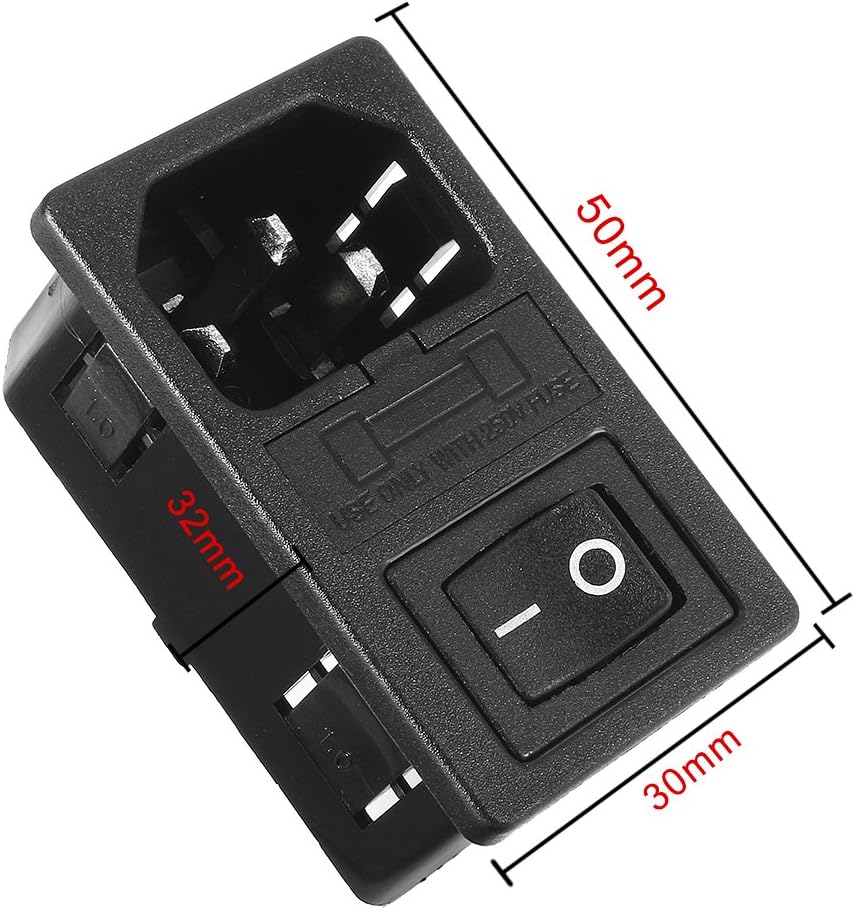
Figure 3.3: Product dimensions (50mm length, 30mm width, 32mm height).
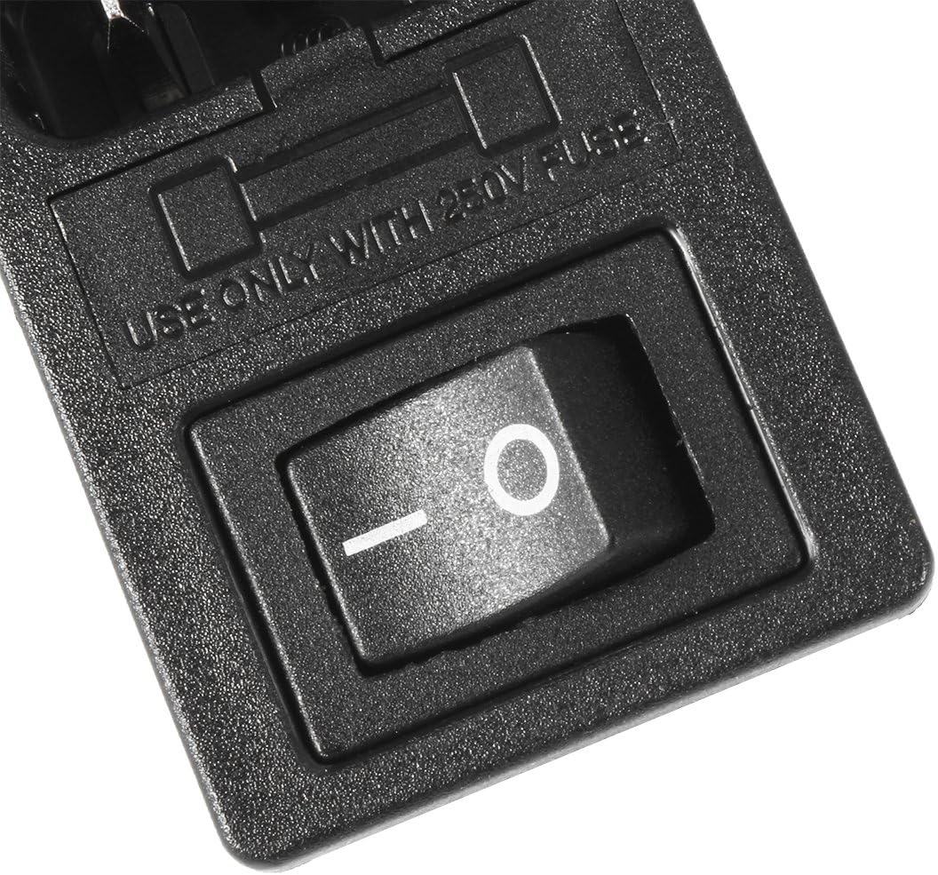
Figure 3.4: Detailed view of the rocker switch and fuse compartment.

Figure 3.5: Detailed view of the screw terminals for wiring.
4. Setup and Installation
Proper installation is crucial for the safe and reliable operation of this power socket. This unit is designed for panel mounting.
4.1. Fuse Installation
- Ensure the power source is disconnected.
- Locate the fuse holder compartment, typically a small drawer or cover next to the IEC inlet.
- Insert a 250V fuse (not included) of the appropriate current rating (e.g., 10A for general use, or lower based on load type as specified in Section 2). The recommended fuse size is 5x20mm.
- Close the fuse holder compartment securely.
4.2. Electrical Wiring
The unit features screw terminals for electrical connections. A common wiring configuration for AC power involves connecting the Live, Neutral, and Ground wires.
- Live (Hot) Wire: The switch is designed to control the live voltage. The incoming live line should be hard-connected to one side of the fuse. The output terminal of the fuse then connects to one side of the rocker switch. The remaining terminal from the switch connects to the live input of your equipment.
- Neutral Wire: The neutral line typically goes directly from the power source to the neutral input of your equipment, bypassing the switch.
- Ground Wire: The center terminal is for ground. This should be connected to the earth ground of your power source and to the metal frame or grounding tab of your equipment for safety.
Note: Always verify wiring with a multimeter before applying power. Incorrect wiring can lead to component failure or safety hazards.
5. Operating Instructions
Operation of the uxcell Inlet Male Power Socket is straightforward:
- Ensure the unit is properly installed and wired, and a suitable fuse is in place.
- Connect a standard IEC C13 power cord (not included) to the IEC C14 inlet on the unit.
- To turn on the connected equipment, press the rocker switch to the 'I' (ON) position.
- To turn off the connected equipment, press the rocker switch to the 'O' (OFF) position.
6. Maintenance
The uxcell Inlet Male Power Socket requires minimal maintenance. Regular checks can ensure continued safe operation.
6.1. Fuse Replacement
If the connected equipment loses power unexpectedly, the fuse may have blown. Follow these steps to replace it:
- Disconnect all power to the unit and the connected equipment.
- Open the fuse holder compartment.
- Carefully remove the blown fuse.
- Insert a new fuse of the exact same type and rating (250V, appropriate amperage). Never use a fuse with a higher rating than specified.
- Close the fuse holder compartment securely.
- Reconnect power and test the unit.
6.2. Cleaning
Wipe the exterior of the unit with a soft, dry cloth. Do not use abrasive cleaners or solvents. Ensure no liquids enter the electrical components.
7. Troubleshooting
| Problem | Possible Cause | Solution |
|---|---|---|
| No power to connected equipment. | Blown fuse. | Replace the fuse (refer to Section 6.1). Ensure the new fuse has the correct rating. |
| No power to connected equipment. | Incorrect or loose wiring. | Disconnect power. Check all electrical connections for proper wiring and tightness (refer to Section 4.2). |
| Switch does not operate correctly. | Internal damage to switch. | The switch may be damaged due to overload or manufacturing defect. Replacement of the entire unit may be necessary. |
| Unit gets excessively warm. | Overload or incorrect load type. | Ensure the connected load does not exceed the specified current ratings for the switch and fuse holder (refer to Section 2). Verify the load type (resistive, inductive, etc.) matches the unit's capabilities. |
8. Specifications
| Feature | Detail |
|---|---|
| Brand | uxcell |
| Model Number | a10121000ux0049 |
| UPC | 781171036745 |
| Connector Type | IEC C14 |
| Actuator Type | Rocker |
| Operation Mode | Manual |
| Operating Voltage | 250 Volts |
| Current Rating | 10 Amps (max), 2 Amps (general) |
| Wattage | 500 watts |
| Contact Type | Normally Open |
| Terminal Type | Screw |
| Material | Plastic, Metal |
| Item Dimensions (L x W x H) | 4.72 x 2.76 x 1.18 inches (approx. 120 x 70 x 30 mm) |
| Item Weight | 0.634 ounces (approx. 18 grams) |
| Date First Available | May 16, 2011 |
9. Warranty and Support
Specific warranty information for this product is not provided in the available documentation. For any product-related inquiries, technical support, or warranty claims, please contact the manufacturer, uxcell, directly through their official channels or the retailer from whom the product was purchased.
You can visit the uxcell store on Amazon for more information: uxcell Amazon Store
Ask a question about this manual
Ask about setup, troubleshooting, compatibility, parts, safety, or missing instructions. Manuals+ will review the question and use this page’s manual context to help answer it.