1. Introduction
This manual provides detailed instructions for the installation, operation, and maintenance of your Thermaltake MAX-3543 Backplane Hot Swap Hard Drive Kit. This unit converts three standard 5.25-inch drive bays into four hot-swappable bays for 3.5-inch SAS/SATA hard drives. It is designed to facilitate easy drive management and expansion within your computer system.
Package Contents
- Thermaltake MAX-3543 Backplane Unit
- Hard Drive Trays (4 units)
- SATA Data Cables (4 units)
- Mounting Screws
- User Manual (this document)
2. Safety Information
Please read and understand all safety instructions before installing or operating the device. Failure to do so may result in personal injury or damage to the equipment.
- Ensure your computer system is powered off and unplugged from the electrical outlet before installation.
- Wear an anti-static wrist strap to prevent electrostatic discharge (ESD) damage to components.
- Handle hard drives and the backplane unit with care to avoid physical damage.
- Do not expose the unit to moisture or extreme temperatures.
- Only use the provided or recommended accessories and cables.
3. Setup and Installation
3.1 Preparing the Unit
The Thermaltake MAX-3543 requires three empty 5.25-inch drive bays in your computer chassis for installation.

Figure 3.1: Front view of the Thermaltake MAX-3543 unit, showcasing the four drive bays and LED indicators.
3.2 Installing the Unit into the Chassis
- Power off your computer and disconnect all cables.
- Open your computer chassis.
- Remove the covers for three consecutive 5.25-inch drive bays from the front of your chassis.
- Slide the MAX-3543 unit into the open 5.25-inch bays from the front until it is flush with the chassis.
- Secure the unit to the chassis using the provided mounting screws on both sides.
3.3 Connecting Power and Data Cables

Figure 3.2: Rear panel of the MAX-3543, showing the dual SATA power connectors, four SATA data ports, and the cooling fan.
- Connect two available SATA power connectors from your power supply unit (PSU) to the two power ports labeled 'POWER1' and 'POWER2' on the rear of the MAX-3543 unit.
- Connect the provided SATA data cables from the four data ports on the rear of the MAX-3543 (labeled 'HD1' to 'HD4') to available SATA ports on your motherboard or RAID controller.
- Ensure all connections are secure.
3.4 Installing Hard Drives into Trays
The MAX-3543 uses individual trays for each hard drive. These trays are compatible with 3.5-inch SAS/SATA hard drives. 2.5-inch drives can also be installed using a compatible 2.5-inch to 3.5-inch adapter (not included).
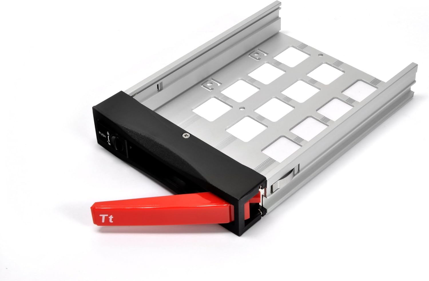
Figure 3.3: An empty hard drive tray, ready for drive installation.

Figure 3.4: A 3.5-inch hard drive securely mounted within its tray.
- Pull out an empty hard drive tray from the MAX-3543 unit by pressing the 'PUSH' button and pulling the handle.
- Place your 3.5-inch hard drive into the tray, aligning the screw holes.
- Secure the hard drive to the tray using the provided screws. Ensure the drive is firmly attached to prevent vibration.
- For 2.5-inch drives, first mount the 2.5-inch drive into a 3.5-inch adapter (if required), then secure the adapter into the tray.
3.5 Inserting Hard Drive Trays

Figure 3.5: A hard drive tray being carefully inserted into one of the bays.
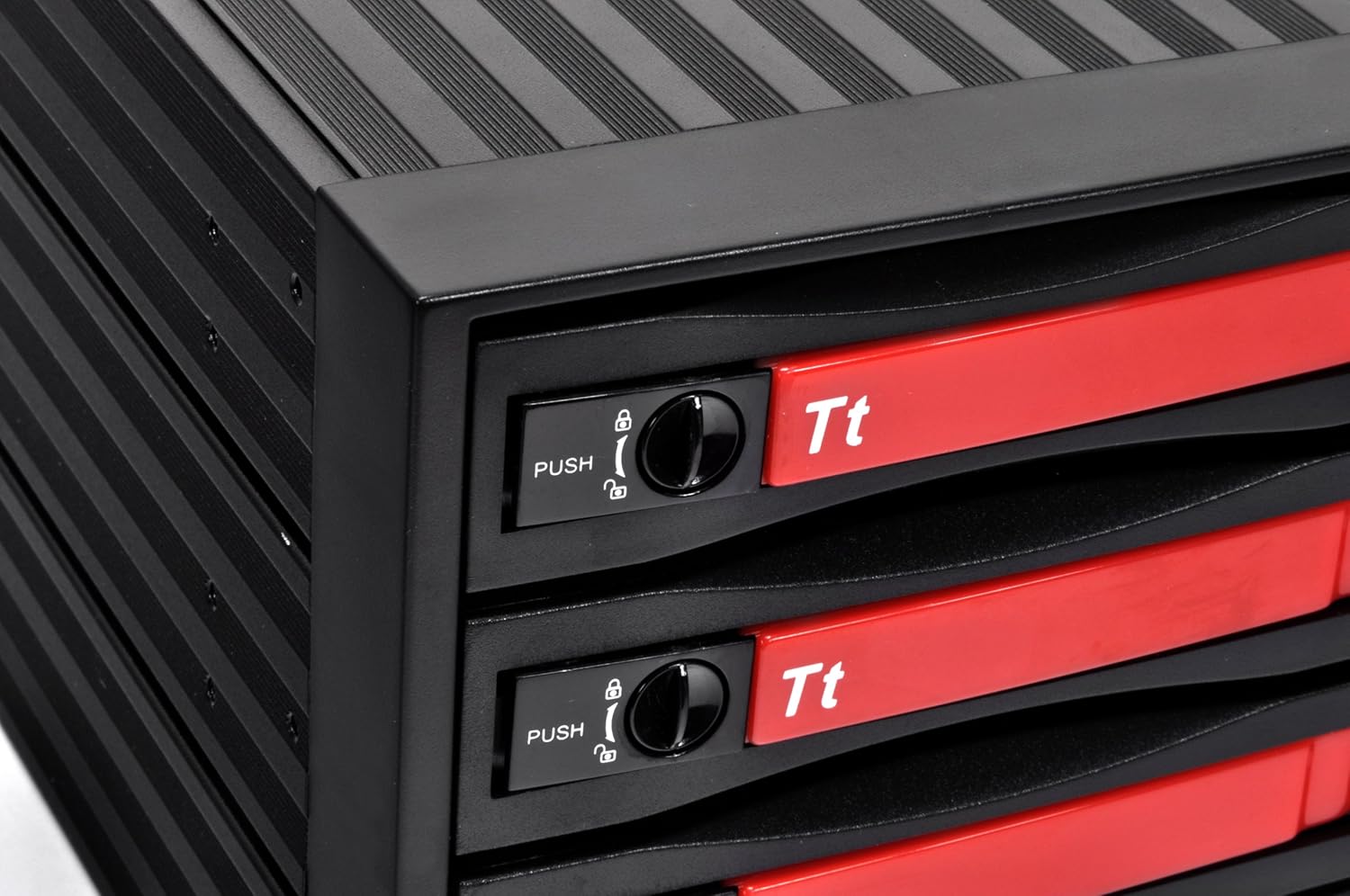
Figure 3.6: The lock mechanism on the drive tray, which secures the drive in place once inserted.
- Gently slide the loaded hard drive tray into an empty bay of the MAX-3543 unit.
- Push the tray in until it clicks into place and the handle is flush with the front panel. The lock mechanism will engage automatically.
- Repeat for all desired hard drives.
- Close your computer chassis and reconnect all cables.
- Power on your computer. The operating system should detect the newly installed drives.
4. Operating Instructions
4.1 LED Indicators

Figure 4.1: Front panel with blue LED indicators for each hard drive (HD1-HD4) and a reset button.
The front panel features individual LED indicators for each hard drive bay (HD1-HD4). These LEDs illuminate to indicate drive activity and status:
- Solid Blue: Hard drive is powered on and idle.
- Flashing Blue: Hard drive is actively reading or writing data.
4.2 Hot-Swapping Drives
The MAX-3543 supports hot-swapping of SAS/SATA drives, allowing you to remove or insert drives while the system is running. However, proper procedure must be followed to prevent data loss.
- Before Removal: Ensure the drive you wish to remove is not actively being used by the operating system. Safely eject or unmount the drive through your operating system's disk management tools. For RAID configurations, consult your RAID controller's documentation for safe drive removal procedures.
- Press the 'PUSH' button on the desired drive tray and pull the handle to release and slide out the tray.
- Remove the old hard drive from the tray and install the new hard drive, securing it with screws.
- Gently slide the tray with the new hard drive back into the bay until it clicks into place.
- The operating system should detect the new drive. You may need to initialize and format the drive through disk management before use.
Important Note:
While the unit supports hot-swapping, the process of screwing and unscrewing drives from the trays means it is not a tool-less hot-swap solution. Always ensure data integrity by safely ejecting drives via software before physical removal.
4.3 Fan Speed Switch

Figure 4.2: The fan speed switch located on the rear panel, offering 'HIGH' and 'LOW' settings.
A fan speed switch is located on the rear of the unit, allowing you to select between 'HIGH' and 'LOW' fan speeds. Adjust this setting based on your cooling needs and noise preferences.
5. Maintenance
5.1 Cleaning
Periodically clean the exterior of the unit with a soft, dry cloth. Ensure the cooling fan on the rear is free from dust buildup to maintain optimal airflow. Do not use liquid cleaners directly on the unit.
5.2 Fan Replacement
The integrated cooling fan is designed for longevity. However, if the fan becomes excessively noisy or ceases to function, it can be replaced. Consult Thermaltake support for compatible replacement fans and detailed replacement instructions.
6. Troubleshooting
- Drives Not Detected:
- Ensure all SATA data and power cables are securely connected to the MAX-3543 and your motherboard/PSU.
- Verify that the hard drive is properly seated and screwed into its tray.
- Check your motherboard's BIOS/UEFI settings to ensure SATA ports are enabled.
- Test the hard drive directly connected to the motherboard to rule out drive failure.
- Excessive Fan Noise:
- Switch the fan speed to 'LOW' using the switch on the rear panel.
- Ensure the fan is free from dust or obstructions.
- If noise persists, consider replacing the fan (refer to Section 5.2).
- LEDs are too Bright:
- While there is no built-in dimmer, some users opt to cover the LEDs with opaque tape if the brightness is disruptive.
- Hot-Swap Issues:
- Always safely eject or unmount drives via software before physical removal to prevent data corruption.
- Ensure your operating system and motherboard/RAID controller fully support hot-swapping.
7. Specifications
| Model Number | RC3400101A |
| Product Dimensions | 6.5 x 7 x 10 inches |
| Item Weight | 3.7 pounds |
| Drive Bay Compatibility | 3 x 5.25-inch external bays (for unit installation) |
| Drive Support | 4 x 3.5-inch SAS/SATA HDDs (2.5-inch drives with adapter) |
| Hard Disk Interface | SAS/SATA |
| Connectivity Technology | SATA |
| Color | Black |
| Manufacturer | Thermaltake USA Direct |
8. Warranty Information
Thermaltake products are manufactured to the highest quality standards. For detailed warranty terms and conditions, please refer to the warranty card included with your product or visit the official Thermaltake website. Keep your proof of purchase for warranty claims.
9. Support
If you encounter any issues or have questions regarding your Thermaltake MAX-3543, please visit the official Thermaltake support website or contact their customer service department for assistance. Support resources often include FAQs, driver downloads, and contact information.


