
Introduction
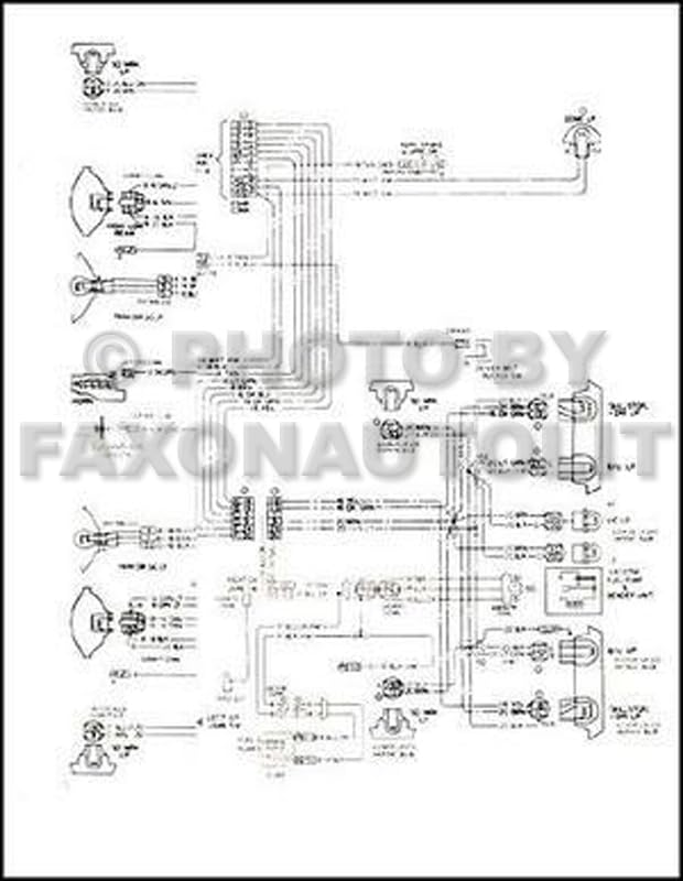
This manual provides comprehensive wiring diagrams for the 1965 Pontiac Tempest, LeMans, and GTO models. It is an invaluable resource for understanding, diagnosing, and repairing the electrical systems of these classic vehicles. The diagrams illustrate the complete electrical circuits, component locations, and wire routing, enabling accurate identification of electrical paths and connections.
The information contained within this reprint is based on original factory specifications, ensuring accuracy and reliability for automotive enthusiasts and professional technicians alike. Proper use of this manual can significantly aid in troubleshooting electrical issues and performing correct repairs or modifications.
This image displays the front cover of the manual, featuring the title and relevant vehicle models.
How to Use This Manual
To effectively utilize this wiring diagram manual, follow these guidelines:
- Identify the System: Locate the specific electrical system or component you are working on (e.g., ignition, lighting, charging).
- Understand Symbols: Familiarize yourself with the electrical symbols used throughout the diagrams. A glossary of common symbols is provided in a dedicated section.
- Trace Circuits: Follow the wire paths from the power source, through components, to ground. Note wire colors and gauge where indicated.
- Reference Component Locations: Use any provided diagrams or descriptions to locate physical components within the vehicle.
- Safety First: Always disconnect the vehicle's battery before performing any electrical work to prevent short circuits or injury.
Understanding the flow of electricity and the function of each component is crucial for accurate diagnosis.
General Wiring Information
The electrical system of your 1965 Pontiac vehicle is a complex network designed to power various functions. Key elements include:
- Power Sources: Battery and alternator provide the necessary electrical energy.
- Fuses and Circuit Breakers: Protective devices that prevent damage from overcurrents.
- Switches: Control the flow of electricity to various circuits.
- Relays: Electrically operated switches that allow a low-current circuit to control a high-current circuit.
- Grounds: Essential return paths for electrical current to complete a circuit.
All wiring is color-coded for identification, and wire gauges are specified to ensure proper current carrying capacity. Refer to the specific diagrams for detailed information on each circuit.
Specific System Diagrams
This manual contains detailed diagrams for the following major electrical systems:
- Charging System: Alternator, voltage regulator, battery, and associated wiring.
- Starting System: Starter motor, solenoid, ignition switch, and related circuits.
- Ignition System: Coil, distributor, spark plugs, and ignition control circuits.
- Lighting System: Headlights, taillights, turn signals, brake lights, interior lights, and their switches.
- Accessory Circuits: Radio, heater/AC, power windows (if equipped), wipers, horn, and other auxiliary components.
- Instrumentation: Gauges, warning lights, and their sending units.
Each diagram is presented clearly, often with component call-outs and wire color legends to assist in tracing circuits.
Electrical System Troubleshooting
When an electrical issue arises, systematic troubleshooting is key. Use the wiring diagrams to:
- Isolate the Problem: Determine which circuit or component is affected.
- Check Power and Ground: Verify that the component is receiving power and has a good ground connection. Use a multimeter for accurate readings.
- Inspect Fuses: Check all relevant fuses for continuity. Replace blown fuses with those of the correct amperage.
- Test Switches and Relays: Confirm proper operation of switches and relays within the circuit.
- Examine Wiring: Look for frayed, corroded, or broken wires. Pay close attention to areas prone to movement or heat.
- Consult Specifications: Compare measured values (voltage, resistance) against the vehicle's electrical specifications.
Always refer to a service manual for specific diagnostic procedures and safety warnings related to your vehicle's electrical system.
Electrical Specifications
While this manual primarily focuses on diagrams, understanding general electrical specifications is vital for proper repair and maintenance. Always cross-reference with a comprehensive service manual for precise values for your specific vehicle configuration.
| Component | Typical Specification |
|---|---|
| Battery Voltage (Nominal) | 12 Volts DC |
| Charging System Voltage | 13.8 - 14.8 Volts DC (Engine Running) |
| Headlight Bulb Type | Sealed Beam (e.g., H6024) |
| Tail/Brake Light Bulb Type | Dual Filament (e.g., 1157) |
| Typical Wire Gauge (Main Power) | 8-10 AWG |
| Typical Wire Gauge (Accessory) | 14-18 AWG |
Always use fuses with the specified amperage rating. Using incorrect fuses can lead to electrical system damage or fire.
Glossary of Symbols
Electrical diagrams use standardized symbols to represent components. A basic understanding of these symbols is essential for interpreting the diagrams correctly. Common symbols include:
- Battery: A series of long and short parallel lines.
- Resistor: A zigzag line.
- Capacitor: Two parallel lines.
- Switch: A break in a line with a movable arm.
- Fuse: A rectangle with a line passing through it.
- Ground: Three decreasing parallel lines or an inverted triangle.
- Lamp/Bulb: A circle with a cross or loop inside.
- Motor: A circle with an 'M' inside.
Refer to the legend provided within the manual's diagrams for specific symbols and their meanings as they may vary slightly between publications.
Important Notices
This wiring diagram manual is a reprint intended for informational and reference purposes only. While efforts have been made to ensure accuracy, the publisher assumes no liability for errors or omissions. Always exercise caution when working with automotive electrical systems.
For critical repairs or if you are unsure about any procedure, it is recommended to consult with a certified automotive technician. This manual does not replace the need for proper tools, safety equipment, or professional training.
All trademarks and copyrights mentioned herein belong to their respective owners.