1. Introduction
The Optex RCTD-20U Wireless Annunciator System is designed to provide reliable wireless detection and alert capabilities for various applications. This system is suitable for monitoring driveways, entry points, and other areas, transmitting signals up to 2,000 feet. It serves as an effective perimeter alert system, notifying users of approaching vehicles or individuals. The system offers multiple tone alerts and adjustable sensitivity levels, supporting up to 12 transmitters for comprehensive coverage.
2. Important Safety Information
- Read all instructions carefully before installation and operation.
- Do not expose the sensor to extreme temperatures or direct water immersion. The sensor is weather-resistant, not waterproof.
- Ensure batteries are inserted with correct polarity.
- Keep out of reach of children.
- Dispose of used batteries according to local regulations.
3. Package Contents
The Optex RCTD-20U system typically includes the following components:
- Wireless Motion Detection Sensor (Transmitter)
- Wireless Annunciator Receiver
- Mounting Hardware (screws, anchors)
- User Manual (this document)
- Note: A 9V battery for the sensor is required and may be included or sold separately.

Figure 3.1: The Optex RCTD-20U system, showing both the wireless receiver and the motion detection sensor.
4. Product Overview
4.1. Wireless Motion Detection Sensor (Transmitter)
This weather-proof unit detects motion and transmits a signal to the receiver. It operates on a 9V battery.

Figure 4.1: Top view of the Optex RCTD-20U motion sensor, showing the detection lens and adjustment options.

Figure 4.2: Side view of the Optex RCTD-20U motion sensor, illustrating its compact design.

Figure 4.3: Back view of the Optex RCTD-20U motion sensor, showing mounting points and battery compartment access.
4.2. Wireless Annunciator Receiver
This unit receives signals from the sensor and produces an audible alert. It features adjustable volume and multiple tone options.
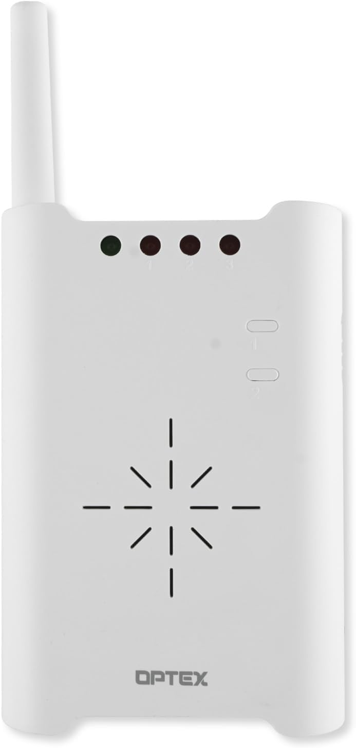
Figure 4.4: Front view of the Optex RCTD-20U receiver, displaying indicator lights and speaker grille.
5. Setup and Installation
5.1. Sensor (Transmitter) Installation
- Battery Installation: Open the battery compartment on the back of the sensor. Insert one 9V battery, ensuring correct polarity. Close the compartment securely.
- Mounting Location: Choose a suitable outdoor location for the sensor, such as a wall, post, or tree. The sensor is weather-proof and designed for outdoor use. Consider areas where approaching vehicles or people will cross the detection beam.
- Mounting: Use the provided mounting hardware to securely attach the sensor. Ensure it is mounted at a height that optimizes detection for the intended targets (e.g., vehicles, pedestrians). The sensor can be easily mounted on most outside surfaces.
- Aiming: Adjust the sensor's angle to achieve the desired detection pattern. The system supports multiple detection patterns for precise aiming. Avoid aiming directly at moving foliage or reflective surfaces that could cause false alarms.
5.2. Receiver Setup
- Power: Plug the receiver into a standard electrical outlet indoors.
- Placement: Place the receiver in a central location within your home or business, ensuring it is within the 2,000-foot transmission range of the sensor. Walls and other obstructions can reduce range.
- Pairing (if necessary): The system is typically pre-paired. If pairing is required, refer to the specific instructions for your model to synchronize the sensor with the receiver.
6. Operating Instructions
6.1. Power On/Off
The receiver typically powers on when plugged in. The sensor is active once the battery is installed. An on-off control may be present on the receiver for convenience.
6.2. Adjusting Volume and Tone
The receiver features adjustable volume controls. Locate the volume buttons or dial on the receiver and adjust to your preferred level. The system also offers three different tone alerts to distinguish between multiple sensors or alert types. Consult the receiver's specific controls to cycle through and select desired tones.
6.3. Sensitivity Levels
The sensor incorporates five different sensitivity levels. Adjusting the sensitivity can help prevent false alarms from small animals or environmental factors while ensuring detection of intended targets. Refer to the sensor's internal or external controls for sensitivity adjustment.
6.4. Understanding Alerts
When motion is detected by the sensor, the receiver will emit an audible alert according to the selected tone and volume. Indicator lights on the receiver may also illuminate to show which zone or sensor has been triggered.
7. Maintenance
7.1. Battery Replacement
The sensor operates on a 9V battery, which typically lasts approximately two years under average use. When the battery is low, the sensor may exhibit reduced range or inconsistent detection. Replace the battery by opening the compartment on the back of the sensor and inserting a new 9V alkaline battery.
7.2. Cleaning
Wipe the exterior of both the sensor and receiver with a soft, damp cloth. Do not use abrasive cleaners or solvents. Ensure the sensor's lens is kept clear of dirt, dust, and spiderwebs for optimal performance.
7.3. Environmental Considerations
While the sensor is weather-proof, extreme weather conditions (heavy snow, ice, direct prolonged sunlight) can affect performance. Periodically check the sensor's mounting and ensure it remains free from obstructions.
8. Troubleshooting
| Problem | Possible Cause | Solution |
|---|---|---|
| No alert from receiver |
|
|
| False alarms |
|
|
| Short transmission range |
|
|
9. Specifications
| Feature | Detail |
|---|---|
| Brand | Optex |
| Model Number | RCTD-20U |
| Power Source (Sensor) | Battery Powered (1 x 9V battery required) |
| Battery Type (Sensor) | Alkaline (average 2-year life) |
| Maximum Transmission Range | Up to 2,000 feet (approx. 600 meters) |
| Mounting Type (Sensor) | Wall Mount |
| Compatible Devices | Cars, Homes/Buildings, Warehouses |
| Product Dimensions | 8.6 x 7.5 x 4.4 inches |
| Item Weight | 1.57 pounds |
| Color | Rust (as per product listing, though product images show white) |
| Features | Adjustable volume, multiple tone alerts, 5 sensitivity levels, weather-proof sensor |
10. Warranty and Support
For warranty information and technical support, please refer to the official Optex website or contact their customer service department. Keep your purchase receipt as proof of purchase for any warranty claims.
Note: Specific warranty terms may vary by region and retailer.


