1. Product Overview
The Optex AX-200TN is a high-performance outdoor dual beam photoelectric detector designed for short-range perimeter security. It features a 200-foot (60-meter) capture area, providing reliable motion detection for various applications. Its robust design ensures accurate detection while minimizing false alarms, making it suitable for both indoor and outdoor environments.

Figure 1: Optex AX-200TN Dual Beam Photoelectric Detector. This image shows the sleek, dark casing of the detector, highlighting its compact and durable design.
2. Key Features
- Dual Beam Technology: Utilizes two synchronized infrared beams to enhance detection accuracy and reduce false alarms caused by small animals or environmental factors.
- Extended Range: Capable of detecting motion up to 200 feet (60 meters), providing wide coverage for various security needs.
- Photoelectric Detection: Ensures precise and reliable detection by sensing interruptions in the infrared beams.
- Weather-Resistant Design: Built to withstand outdoor conditions, ensuring consistent performance in diverse weather.
- Adjustable Settings: Offers customizable sensitivity options to tailor detection parameters to specific environmental requirements and minimize unwanted triggers.
- Easy Installation: Designed for straightforward setup and alignment.
3. Setup and Installation
Proper installation and alignment are crucial for optimal performance of the AX-200TN detector. Follow these general guidelines:
- Mounting Location: Choose a stable, flat surface for mounting both the transmitter and receiver units. Ensure they are aligned directly opposite each other within the 200-foot range.
- Height: Mount the units at an appropriate height to ensure the beams are not obstructed by common objects or terrain.
- Wiring: Connect the power supply and alarm output wiring according to the detailed wiring diagram provided in the full product manual. Ensure all connections are secure and properly insulated.
- Alignment: Carefully align the transmitter and receiver units. The AX-200TN typically includes visual or audible indicators to assist with precise beam alignment. Adjust until a strong, stable signal is achieved.
- Sensitivity Adjustment: Adjust the detection sensitivity as needed to prevent false alarms from environmental factors while ensuring reliable detection of intended targets.
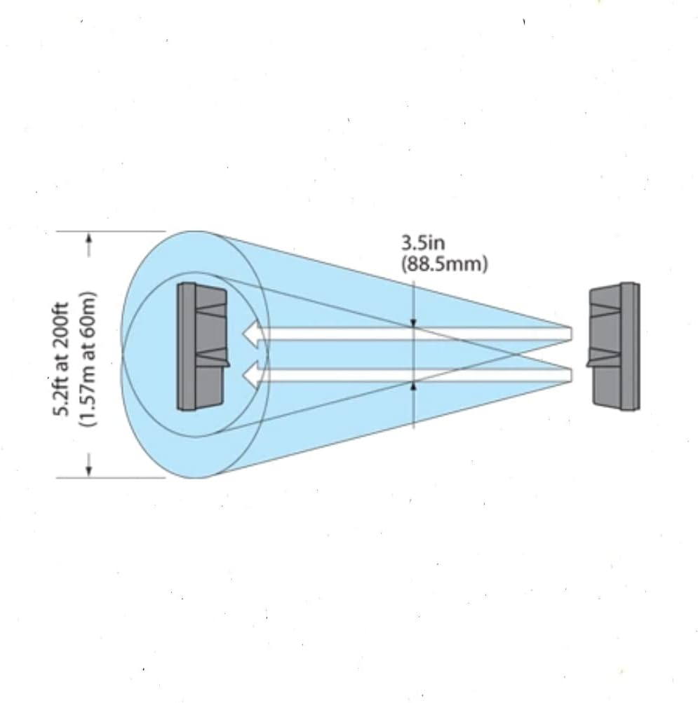
Figure 2: Beam Alignment Diagram. This diagram illustrates the dual infrared beams emitted by the detector, showing how they create a detection zone and the importance of precise alignment between the transmitter and receiver units for effective operation.
4. Operating Instructions
Once installed and aligned, the Optex AX-200TN operates by continuously emitting and receiving two infrared beams. When both beams are simultaneously interrupted, the detector triggers an alarm signal. This dual beam mechanism significantly reduces the likelihood of false alarms caused by single beam obstructions like falling leaves or small animals.
- Power On: Ensure the detector is properly powered. An indicator light typically confirms power status.
- Detection: The unit will continuously monitor the detection zone.
- Alarm Output: Upon detection of an intrusion, the detector will activate its alarm output, which can be connected to a security panel, siren, or other monitoring device.
- Status Indicators: Refer to the device's indicator lights for status information, such as power, alarm, and beam alignment strength.
5. Maintenance
Regular maintenance ensures the long-term reliability and performance of your AX-200TN detector.
- Clean Lenses: Periodically clean the optical lenses of both the transmitter and receiver units using a soft, clean cloth to remove dust, dirt, or spiderwebs that may obstruct the beams.
- Check Alignment: Verify that the units remain properly aligned. Environmental shifts, such as ground settling or strong winds, can sometimes affect alignment. Re-align if necessary.
- Inspect Wiring: Check all wiring connections for any signs of wear, corrosion, or damage. Ensure they are secure.
- Clear Obstructions: Keep the detection path clear of any growing vegetation, debris, or other potential obstructions that could interfere with the beams.
6. Troubleshooting
If you encounter issues with your Optex AX-200TN, consider the following common troubleshooting steps:
- False Alarms:
- Check for partial beam obstructions (e.g., swaying branches, tall grass, large birds).
- Re-align the beams to ensure optimal signal strength.
- Adjust sensitivity settings to a lower level if environmental factors are causing frequent false triggers.
- No Detection:
- Verify power supply to both units.
- Ensure beams are perfectly aligned. Use the alignment indicators if available.
- Clean the optical lenses thoroughly.
- Check wiring connections for continuity and proper installation.
- Confirm that the detection range is not exceeded.
- Intermittent Operation:
- Inspect for loose wiring connections.
- Check for unstable mounting surfaces.
- Ensure consistent power supply.
7. Specifications
| Attribute | Value |
|---|---|
| Product Dimensions | 8 x 9 x 3 inches |
| Item Weight | 1 pounds |
| ASIN | B003V1FC6C |
| Item Model Number | AX-200TN |
| Manufacturer | OPTEX |
| Date First Available | January 16, 2009 |
8. Warranty and Support
For detailed warranty information, technical support, or service inquiries regarding your Optex AX-200TN Dual Beam Photoelectric Detector, please refer to the official Optex website or contact their customer service directly. Keep your purchase receipt for warranty claims.
Note: This manual provides general information. Always refer to the complete official product manual for detailed installation instructions, safety precautions, and specific technical specifications.


