
Robertshaw 710-502
Robertshaw 710-502 Millivolt Gas Valve Instruction Manual
Model: 710-502
1. Introduction
This manual provides comprehensive instructions for the safe and efficient installation, operation, and maintenance of the Robertshaw 710-502 Millivolt Gas Valve. Please read this manual thoroughly before attempting any installation or operation to ensure proper function and safety.
2. Important Safety Information
WARNING: Improper installation, adjustment, alteration, service, or maintenance can cause property damage, injury, or death. Read the installation, operating, and maintenance instructions thoroughly before installing or servicing this equipment.
- Installation and service must be performed by a qualified installer, service agency, or gas supplier.
- Always turn off the gas supply at the main shut-off valve before servicing the appliance.
- Check for gas leaks using a soap solution after any gas connection is made. NEVER use an open flame to check for leaks.
- Ensure adequate ventilation in the area where the gas valve is installed.
- Do not operate the valve if any part has been submerged in water. Immediately call a qualified service technician to inspect the appliance and to replace any part of the control system and any gas control which has been submerged in water.
3. Product Features
- Compact, low-profile design for low capacity space heater applications.
- Electrical rating range from 250 mV to 750 mV.
- Suitable for various gas types: natural, manufactured, mixed, liquefied petroleum (LP), and LP gas/air mixtures.
- Equipped with three-position 1/2-inch outlets.
- Features 1/4-inch pilot outlet tubing.
- Standard NEMA terminals for electrical connections.
- Gas cock dial with OFF-PILOT-ON markings.
- Integrated inlet filtered screen.
- RoHS-compliant unit.
4. Components Overview
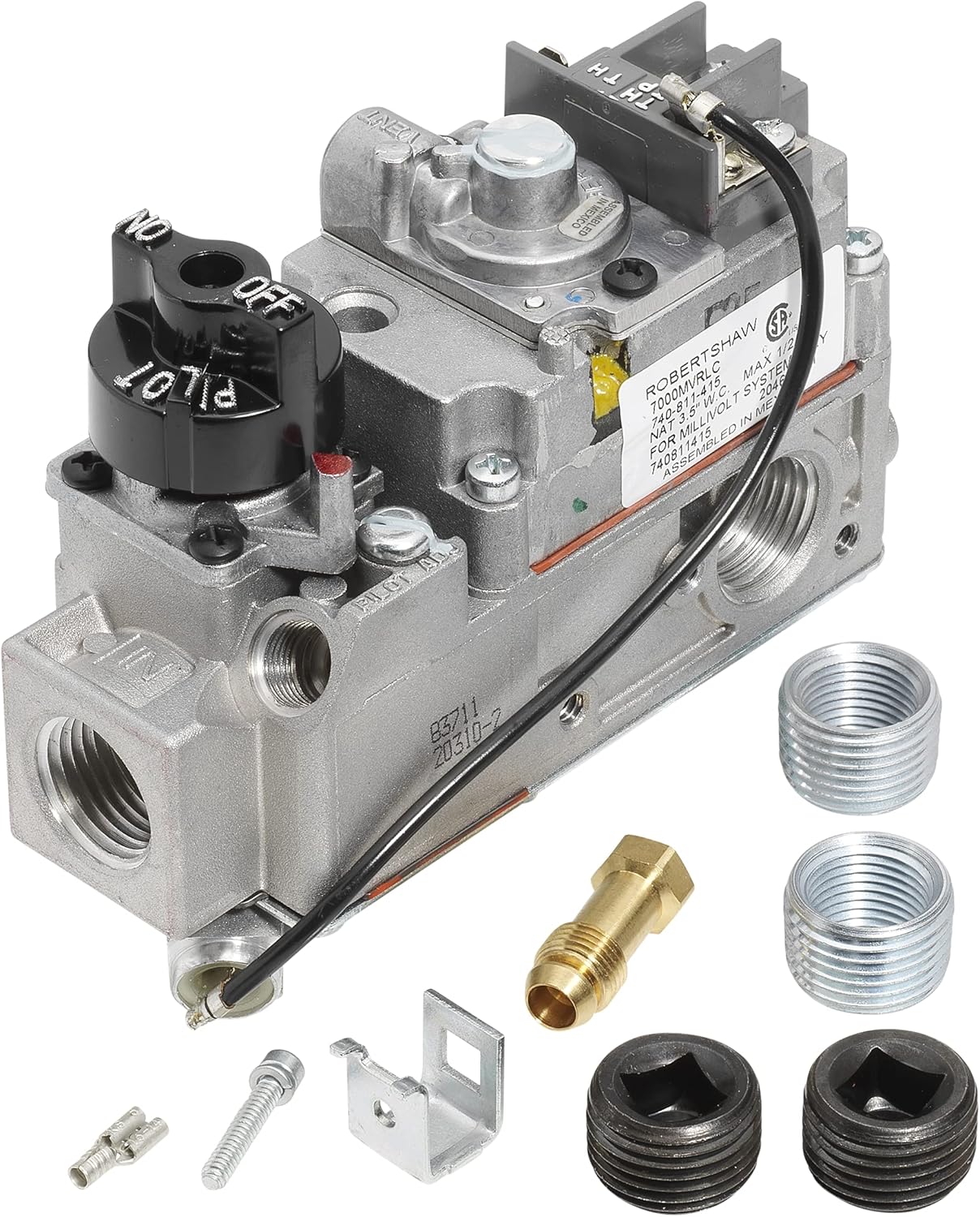
Figure 1: Front view of the Robertshaw 710-502 Gas Valve, showing the control knob, inlet, outlets, and electrical terminals. Various fittings are also displayed.

Figure 2: Back view of the Robertshaw 710-502 Gas Valve, highlighting the electrical connections for the millivolt system.
The Robertshaw 710-502 gas valve consists of several key components:
- Manual Gas Cock: The black knob with OFF-PILOT-ON positions for controlling gas flow.
- Automatic Pilot Safety Valve: Ensures the pilot flame is present before allowing gas to the main burner.
- Pilot Outlet: Connection point for the pilot gas line.
- Pilot Gas Filter: Filters impurities from the pilot gas supply.
- Pilot Adjusting Key: Used to adjust the pilot flame.
- Inlet Connection: Where the main gas supply connects to the valve.
- Outlet Connections: Where gas flows to the main burner.
- Electrical Terminals (TH, TP, TH/TP): Connections for the thermostat and thermopile/thermocouple.
5. Installation and Setup
5.1 Pre-Installation Checks
- Verify that the gas type (Natural Gas or LP Gas) matches the valve's configuration.
- Ensure all necessary tools and additional fittings (if required) are available.
- Confirm that the appliance's BTU capacity does not exceed the valve's 70,000 BTU capacity.
5.2 Mounting the Valve
The Robertshaw 710-502 valve can be mounted in any position except upside down. Secure the valve firmly using appropriate mounting hardware to prevent vibration or movement.
5.3 Gas Connections
- Turn off the main gas supply to the appliance.
- Apply a suitable pipe thread sealant to all male pipe threads.
- Connect the main gas supply line to the valve's inlet connection (marked 'IN').
- Connect the main burner gas line(s) to the valve's outlet connections. The valve has 3-position outlets for flexibility.
- Connect the pilot gas tubing to the pilot outlet.
- After all gas connections are made, turn on the main gas supply and check for leaks using a soap solution. Bubbles indicate a leak. Tighten connections as necessary.
5.4 Electrical Connections (Millivolt System)
Connect the thermostat and thermopile/thermocouple wires to the appropriate terminals (TH, TP, TH/TP) as per the appliance manufacturer's wiring diagram. Ensure all connections are secure and free from shorts.
5.5 Gas Type Conversion (Natural to LP Gas)
Regulated 710 series gas valves can be converted from natural gas to LP gas by using the appropriate replacement pressure regulators. Consult the ordering chart for specific regulator models and follow the instructions provided with the replacement regulator for safe conversion. This procedure should only be performed by a qualified technician.
6. Operating Instructions
6.1 Lighting the Pilot
- Ensure the main gas supply to the appliance is ON.
- Turn the control knob to the 'OFF' position and wait five (5) minutes to clear any gas. If you smell gas, STOP! Follow the safety instructions in Section 2.
- Turn the control knob to the 'PILOT' position.
- Depress the control knob fully and hold. Immediately light the pilot burner with a match or igniter. Continue to hold the knob for about 60 seconds after the pilot lights.
- Release the knob. If the pilot goes out, repeat steps 2-4.
- Once the pilot remains lit, turn the control knob to the 'ON' position.
6.2 Operating the Main Burner
After the pilot is lit and the control knob is in the 'ON' position, the main burner will operate automatically based on the thermostat's call for heat.
6.3 Shutting Down the Appliance
To turn off the main burner, set the thermostat to its lowest setting. To turn off the entire appliance (including the pilot), turn the control knob to the 'OFF' position.
7. Maintenance
Regular maintenance ensures the longevity and safe operation of your gas valve. It is recommended that a qualified service technician perform annual inspections.
- Leak Checks: Periodically check all gas connections for leaks using a soap solution.
- Pilot Flame Inspection: Ensure the pilot flame is strong and stable. If it appears weak or erratic, it may indicate a dirty pilot orifice or low gas pressure.
- Filter Screen: The inlet filtered screen helps prevent debris from entering the valve. If gas flow is restricted, this screen may need inspection and cleaning by a qualified technician.
8. Troubleshooting
| Problem | Possible Cause | Solution |
|---|---|---|
| Pilot will not light or stay lit. | No gas supply; Dirty pilot orifice; Faulty thermopile/thermocouple; Loose electrical connections. | Check gas supply; Clean pilot orifice; Test/replace thermopile/thermocouple; Secure connections. |
| Main burner does not light. | Pilot not lit; Thermostat not calling for heat; Faulty gas valve; Loose electrical connections. | Light pilot; Check thermostat setting; Inspect/replace gas valve; Secure connections. |
| Gas odor detected. | Gas leak. | Immediately turn off gas supply, ventilate area, and call a qualified technician. DO NOT operate appliance. |
For issues not listed or if troubleshooting steps do not resolve the problem, contact a qualified service technician.
9. Specifications
| Specification | Value |
|---|---|
| Brand | Robertshaw |
| Model Number | 710-502 |
| Valve Type | Gas Valve |
| BTU Capacity | 70,000 BTU |
| Electrical Rating | 250 mV to 750 mV |
| Inlet Connection Size | 0.5 Inches |
| Inlet Connection Type | Flare or Compression |
| Outlet Connection Size | 0.5 Inches |
| Outlet Connection Type | FNPT |
| Number of Ports | 3 |
| Item Dimensions (L x W x H) | 3 x 3 x 4.13 inches |
| Item Weight | 1.7 pounds |
| UPC | 662013634278, 796299765286 |
10. Warranty and Support
For warranty information and technical support, please refer to the official Robertshaw website or contact their customer service department. Keep your purchase receipt as proof of purchase for any warranty claims.
Robertshaw Contact Information: Please visit www.robertshaw.com for the most current contact details and support resources.
Related Documents - 710-502
 |
Robertshaw Gas Valve Cross Reference Guide A comprehensive guide to Robertshaw gas valves, including a cross-reference tool for thousands of parts. This document details various models such as manual, hydraulic, 24-volt combination, 2-stage, diaphragm, line voltage, and millivolt gas valves, providing specifications, model numbers, and applications. |
 |
Robertshaw 700 Series Gas Heating Controls Installation Manual Installation and service manual for Robertshaw 700 Series Gas Heating Controls. Includes specifications, piping, wiring, and maintenance instructions for manual, millivolt, hydraulic, 24V, and line voltage models. |
 |
Robertshaw 720 Series Dual Valve Gas Heating Controls Installation Data Installation and service instructions for the Robertshaw 720 Series Convertible/Step Opening Dual Valve Gas Heating Controls, including specifications, wiring, operation, and troubleshooting. |
 |
Robertshaw HVACR Heating Catalog: Thermostats, Gas Valves, and Components Comprehensive catalog from Robertshaw detailing HVACR heating components, including Pro-Series wall thermostats, various gas valves (millivolt, 24V, universal), ignitors, pilots, and accessories. Find product specifications, model numbers, and cross-references for professional installation and replacement. |
 |
Robertshaw 2374 Series Air Pressure Sensing Switches Explore the Robertshaw 2374 Series Air Pressure Sensing Switches, featuring pneumatic, air pressure sensing, and manual reset models. This document details their applications, features, benefits, and provides a comprehensive cross-reference guide for replacement parts from various manufacturers. |
 |
Troubleshooting and Operating Guide: Robertshaw Unitrol Gas Valve Comprehensive troubleshooting, operating, and maintenance guide for the Robertshaw Unitrol gas valve used in stock tank heaters. Includes re-calibration and testing procedures. |
Ask a question about this manual
Ask about setup, troubleshooting, compatibility, parts, safety, or missing instructions. Manuals+ will review the question and use this page’s manual context to help answer it.