Introduction
Welcome to the Greenlee DM-810A True RMS Digital Multimeter user manual. This document provides essential information for the safe and effective operation, maintenance, and troubleshooting of your device. The DM-810A is designed for accurate measurement of AC/DC voltage, AC/DC current, resistance, capacitance, frequency, and continuity, making it a versatile tool for electrical professionals.
Safety Information
To ensure safe operation and service of the meter, follow these instructions. Failure to observe these warnings can result in severe injury or death.
- Always read and understand the entire instruction manual before using the meter.
- Do not exceed the maximum input limits for any function.
- Use caution when working with voltages above 30V AC RMS, 42V peak, or 60V DC. These voltages pose a shock hazard.
- Always use the proper terminals, function, and range for your measurements. The DM-810A features a Beep-Jack audible and visible warning to guard against improper A and mA terminal plug-in.
- Inspect test leads for damaged insulation or exposed metal before each use. Replace if damaged.
- Do not use the meter if it appears damaged or if the case is open.
- Ensure the battery cover is securely closed before operation.
- Adhere to local and national safety codes. Use personal protective equipment (PPE) such as approved safety glasses and electrically insulated gloves when necessary.
Product Overview
This section identifies the key parts and controls of your Greenlee DM-810A multimeter.

Figure 1: Front view of the Greenlee DM-810A Digital Multimeter, showing the display, function selector dial, and input jacks.
- Display: Large LCD for clear readings, often with dual display capability.
- Function Selector Dial: Used to select the desired measurement function (e.g., V~, V-, A~, A-, Ω, CAP, Hz, Continuity).
- Input Jacks:
- COM: Common (negative) input for all measurements.
- VΩHz: Positive input for voltage, resistance, frequency, and capacitance measurements.
- mAμA: Positive input for milliampere and microampere current measurements.
- A: Positive input for ampere current measurements.
- Buttons:
- SELECT: Toggles between functions on a single dial position (e.g., AC/DC voltage, diode/continuity).
- RANGE: Manually selects measurement range or returns to auto-ranging.
- △: Delta function for relative measurements.
- HOLD: Freezes the current display reading.
Setup
Battery Installation
The Greenlee DM-810A requires batteries for operation. Refer to the back of the meter for the battery compartment. Use a screwdriver to open the compartment, insert the specified batteries (typically AA or 9V, check the compartment label), observing correct polarity, and then securely close the cover.
Connecting Test Leads
Always ensure test leads are properly connected before taking measurements.
- Insert the black test lead into the COM (common) input jack.
- Insert the red test lead into the appropriate positive input jack based on the measurement you intend to make:
- For voltage, resistance, capacitance, or frequency, use the VΩHz jack.
- For milliampere or microampere current, use the mAμA jack.
- For ampere current, use the A jack.
- The meter's Beep-Jack feature will provide an audible and visible alert if the function selector is set to a current measurement (A or mA) but the test lead is incorrectly plugged into a voltage/resistance jack, or vice-versa. This helps prevent damage to the meter and ensures correct setup.
Operating Instructions
This section details how to perform various measurements with your DM-810A multimeter.
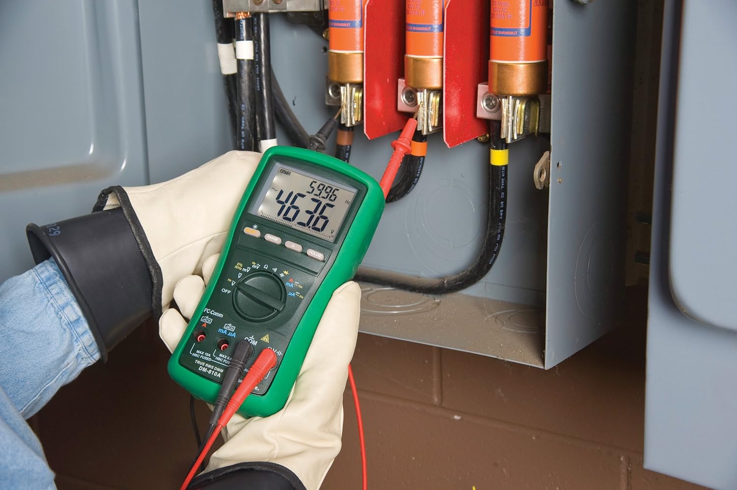
Figure 2: The Greenlee DM-810A Digital Multimeter being used to take measurements within an electrical panel, demonstrating practical application.
Measuring AC/DC Voltage
- Set the function selector to V~ (AC Voltage) or V- (DC Voltage). Use the SELECT button to toggle if both are on one position.
- Connect the black test lead to COM and the red test lead to VΩHz.
- Connect the test probes in parallel across the circuit or component to be measured.
- Read the voltage value on the display.
Measuring AC/DC Current
Important: Current measurements require the meter to be connected in series with the circuit. Ensure the circuit is de-energized before connecting the meter.
- De-energize the circuit.
- Set the function selector to A~ (AC Current) or A- (DC Current), or mA~ / mA-.
- Connect the black test lead to COM. Connect the red test lead to mAμA for small currents or A for larger currents (up to 10A). The Beep-Jack warning will activate if leads are in the wrong jacks for the selected function.
- Open the circuit where the current is to be measured and connect the meter in series.
- Re-energize the circuit and read the current value.
- De-energize the circuit before disconnecting the meter.
Measuring Resistance (Ω)
- De-energize the circuit or component.
- Set the function selector to Ω.
- Connect the black test lead to COM and the red test lead to VΩHz.
- Connect the test probes across the component.
- Read the resistance value.
Measuring Capacitance (CAP)
- Ensure the capacitor is fully discharged before measurement.
- Set the function selector to CAP.
- Connect the black test lead to COM and the red test lead to VΩHz.
- Connect the test probes across the capacitor terminals.
- Read the capacitance value.
Measuring Frequency (Hz)
- Set the function selector to Hz.
- Connect the black test lead to COM and the red test lead to VΩHz.
- Connect the test probes across the signal source.
- Read the frequency value.
Continuity Test
- De-energize the circuit or component.
- Set the function selector to the continuity symbol (often shared with diode test, use SELECT to toggle).
- Connect the black test lead to COM and the red test lead to VΩHz.
- Connect the test probes across the circuit path or component.
- An audible beep indicates continuity (low resistance). The display will show the resistance value.
Maintenance
Cleaning
Wipe the meter with a damp cloth and mild detergent. Do not use abrasives or solvents. Ensure the meter is completely dry before use.
Battery Replacement
When the battery indicator appears on the display, replace the batteries immediately to ensure accurate readings. Follow the battery installation steps outlined in the Setup section.
Fuse Replacement
If the current measurement functions cease to work, the internal fuses may need replacement. Refer to the meter's internal diagram (usually accessible by opening the battery compartment or back casing) for fuse specifications and replacement instructions. Always replace fuses with those of the specified type and rating to maintain safety and performance.
Troubleshooting
This section provides solutions for common issues encountered during the operation of your DM-810A multimeter.
| Problem | Possible Cause | Solution |
|---|---|---|
| No display or dim display | Dead or low batteries | Replace batteries. |
| Incorrect readings | Incorrect function/range selected; Damaged test leads; External interference | Verify function and range; Inspect and replace test leads; Move away from strong electromagnetic fields. |
| Current measurement not working | Blown fuse; Incorrect lead connection | Check and replace fuses; Ensure leads are in the correct A or mA jacks. |
| Beep-Jack warning active | Test leads connected to incorrect input jacks for the selected function | Adjust test lead connections to match the selected function on the dial. |
| Continuity test not beeping | Open circuit; High resistance | Ensure the circuit is closed; Check for breaks in the circuit or component. |
Technical Specifications
The following table outlines the key technical specifications for the Greenlee DM-810A Digital Multimeter.
| Feature | Value |
|---|---|
| Brand | Greenlee |
| Model | DM-810A |
| Measurement Type | True RMS Digital Multimeter |
| Power Source | Battery Powered |
| Style | Digital |
| Item Weight | 16 ounces (1 pound) |
| Product Dimensions (L x W x H) | 10 x 10 x 12 inches |
| Certifications | CE, CSA, UL |
| UPC | 783310087434 |
Warranty and Support
Warranty Information
The Greenlee DM-810A Digital Multimeter comes with a 1-year manufacturer's warranty. This warranty covers defects in materials and workmanship under normal use. Please retain your proof of purchase for warranty claims.
Customer Support
For technical assistance, warranty service, or to inquire about replacement parts, please contact Greenlee customer support. Refer to the official Greenlee website or product packaging for the most current contact information.


