1. Introduction
This manual provides essential information for the installation, operation, and maintenance of the Cisco Catalyst WS-C2960S-24TS-L 2960 Series 24-Port Gigabit Ethernet Switch. The Cisco Catalyst 2960-S and 2960 Series Switches are designed to provide reliable network performance and availability, supporting business applications and security services. These switches are suitable for growing businesses requiring optimized network bandwidth and fast, reliable application delivery.
2. Setup
2.1 Unpacking and Inspection
Carefully unpack the switch and inspect it for any signs of damage during shipping. Ensure all components listed in the packing list are present. If any items are missing or damaged, contact your vendor immediately.
2.2 Site Preparation
Before installation, ensure the installation site meets the following requirements:
- Adequate ventilation to prevent overheating.
- Stable power source (240 Volts).
- Operating temperature within 0°C to 40°C (32°F to 104°F).
- Sufficient space for cable routing and maintenance access.
2.3 Mounting the Switch
The switch can be mounted in a standard 19-inch equipment rack or placed on a flat, stable surface. For rack mounting, use the provided rack-mount kit and secure the switch firmly. Ensure proper grounding.
2.4 Connecting Power
Connect the power cord to the AC power receptacle on the rear of the switch and then to a grounded AC outlet. The switch will power on automatically.
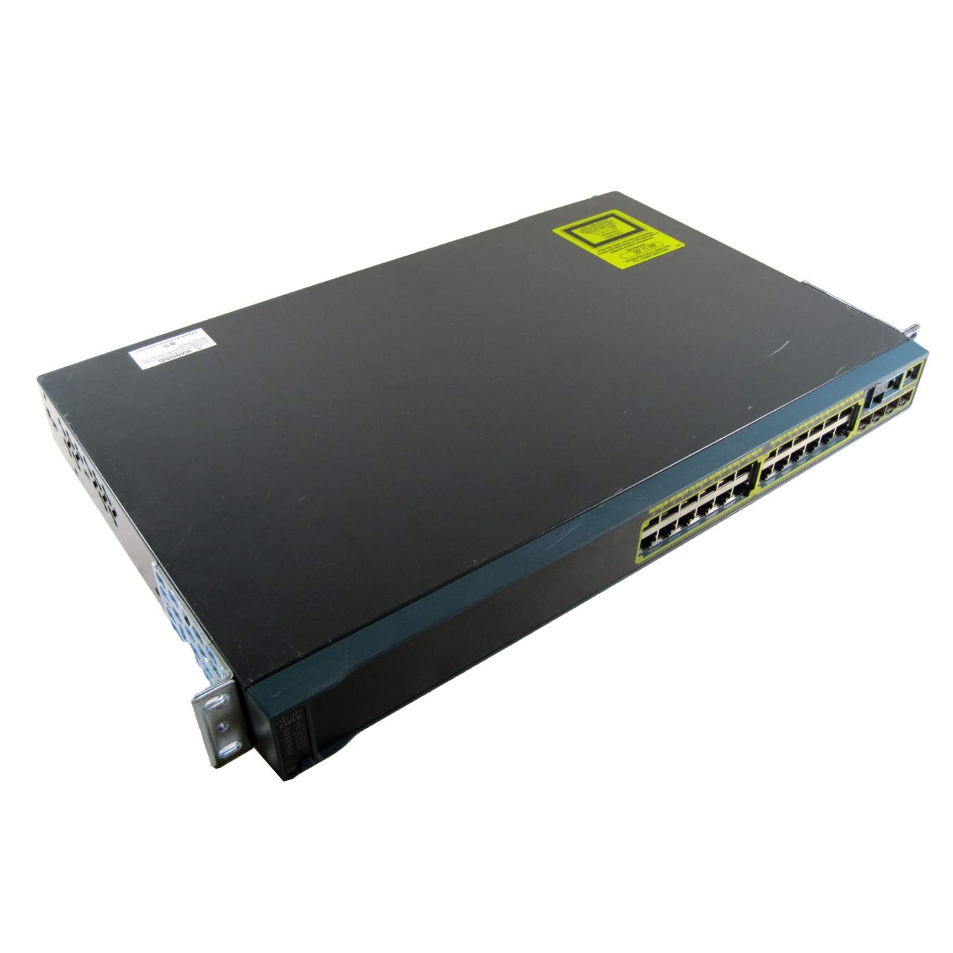
Figure 1: Rear view of the Cisco Catalyst WS-C2960S-24TS-L switch, illustrating the power input, console port, and other interfaces. This view helps identify connection points for initial setup.
2.5 Network Connections
Connect network devices (computers, servers, other switches) to the 24 RJ-45 Gigabit Ethernet ports using standard Ethernet cables. For uplink connections or stacking, utilize the SFP/SFP+ expansion slots and stack ports as required.
3. Operation
3.1 Initial Configuration
Upon initial power-up, the switch will perform a self-test. Access the switch's command-line interface (CLI) via the console port or through a network connection using Telnet or SSH for configuration. Refer to the Cisco IOS Software Configuration Guide for detailed configuration procedures.
3.2 LED Indicators
Monitor the LED indicators on the front panel to check the status of the switch and its ports. Common indicators include:
- System LED: Indicates overall system status (e.g., green for normal operation, amber for fault).
- Port Status LEDs: Indicate link activity, speed, and duplex status for each port.
- Stack LED: Indicates the status of the stacking connection (if applicable).
3.3 Basic Network Management
The switch supports various management protocols, including SNMP, Telnet, SSH, and a web-based interface (if enabled). Use these tools to monitor network traffic, configure VLANs, manage security settings, and perform firmware upgrades.
4. Maintenance
4.1 Regular Cleaning
Periodically clean the exterior of the switch with a soft, dry cloth. Ensure ventilation openings are free from dust and debris to maintain proper airflow and prevent overheating.
4.2 Firmware Updates
Regularly check the Cisco website for the latest firmware updates. Applying updates can improve performance, add new features, and address security vulnerabilities. Follow Cisco's recommended procedures for firmware upgrades to avoid service interruptions.
4.3 Environmental Monitoring
Ensure the operating environment remains within the specified temperature and humidity ranges. Extreme conditions can affect the switch's reliability and lifespan.
5. Troubleshooting
5.1 No Power
- Verify the power cord is securely connected to both the switch and the power outlet.
- Check if the power outlet is functional by plugging in another device.
- Ensure the power source provides the correct voltage (240 Volts).
5.2 No Link on Port
- Check the Ethernet cable for damage and ensure it is properly seated at both ends.
- Verify the connected device is powered on and functioning correctly.
- Try a different port on the switch or a different cable.
- Check the port configuration on the switch (e.g., speed, duplex settings).
5.3 Network Connectivity Issues
- Confirm IP addressing and subnet mask configurations on connected devices and the switch.
- Check for VLAN configuration errors if VLANs are in use.
- Review switch logs for error messages or port flapping events.
- Perform a basic ping test from a connected device to the switch's IP address.
6. Specifications
| Feature | Detail |
|---|---|
| Model Number | WS-C2960S-24TS-L |
| Brand | Cisco |
| Ports | 24 x RJ-45 Gigabit Ethernet, Stack Port, 5 x Expansion Slots (SFP/SFP+) |
| Interface Type | RJ45, SFP, PoE, PoE+, SFP+ |
| Data Transfer Rate | 1000 Megabits Per Second (Gigabit Ethernet) |
| Voltage | 240 Volts |
| Upper Temperature Rating | 40 Degrees Celsius |
| Product Dimensions | 17.52 x 11.77 x 1.77 inches |
| Item Weight | 11.79 pounds (5.36 Kilograms) |
| Case Material | Plastic |
| Color | Black |
7. Warranty and Support
7.1 Warranty Information
This product comes with a 30-day warranty for defective reasons only. Please retain your proof of purchase for warranty claims. The warranty covers manufacturing defects under normal use conditions.
7.2 Technical Support
For technical assistance, product documentation, or to report issues, please visit the official Cisco support website or contact your authorized Cisco reseller. Ensure you have your product model number (WS-C2960S-24TS-L) and serial number available when seeking support.
Note: Cisco's official website (www.cisco.com/support) is the primary resource for comprehensive documentation and support services.


