1. Introduction
The TP-Link TL-PoE10R is an 802.3af compliant Gigabit Power over Ethernet (PoE) Splitter designed to deliver power and data to non-PoE devices over a single Ethernet cable. This device allows you to expand your network to locations where power outlets are not readily available, providing flexible deployment options for various network devices.
Key features include:
- IEEE 802.3af compliance for broad compatibility.
- Ability to deliver power up to approximately 100 meters (325 feet).
- Gigabit Ethernet ports for high-speed data transfer.
- Selectable DC power output options: 5V, 9V, or 12V.
- Plug-and-Play functionality, requiring no complex configuration.
2. Package Contents
Verify that your package contains the following items:
- TP-Link TL-PoE10R PoE Splitter
- Power Adapter
- Ethernet Cable

Image: The TL-PoE10R PoE Splitter shown within its retail packaging, indicating the product and included accessories.
3. Product Overview
The TL-PoE10R PoE Splitter features a compact design with clearly labeled ports and indicators for easy installation and monitoring.

Image: An angled view of the TP-Link TL-PoE10R PoE Splitter, highlighting its compact black casing and port layout.
3.1 Front Panel
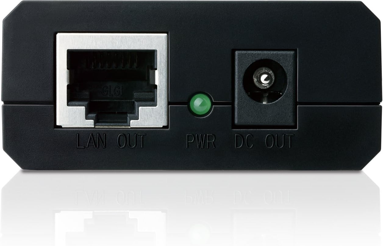
Image: A detailed view of the front panel of the PoE Splitter, showing the LAN OUT Ethernet port, the green PWR LED indicator, and the DC OUT power jack.
- LAN OUT: Gigabit Ethernet port for connecting to a non-PoE network device (e.g., IP camera, wireless access point).
- PWR LED: Indicates the power status of the splitter. Green light signifies normal operation.
- DC OUT: Power output jack for connecting to the power input of the non-PoE device.
3.2 Rear Panel

Image: A detailed view of the rear panel of the PoE Splitter, showing the voltage selection switch (12V, 9V, 5V) and the POWER+DATA IN Ethernet port.
- Voltage Selector (12V, 9V, 5V): A switch to select the desired DC output voltage for the connected device. Ensure this matches the voltage requirement of your device.
- POWER+DATA IN: Gigabit Ethernet port for connecting to a Power Sourcing Equipment (PSE) such as a PoE switch or PoE injector. This port receives both power and data.
4. Setup Guide
Follow these steps to properly install and connect your TL-PoE10R PoE Splitter:
- Determine Device Voltage: Identify the required input voltage (5V, 9V, or 12V) of the non-PoE device you intend to power. This information is typically found on the device's label or in its user manual.
- Set Splitter Voltage: On the rear panel of the TL-PoE10R, use the voltage selector switch to match the required voltage of your device. Caution: Setting an incorrect voltage may damage your device.
- Connect PoE Source: Connect an Ethernet cable from a PoE switch or PoE injector (e.g., TP-Link TL-POE150S) to the POWER+DATA IN port on the rear panel of the TL-PoE10R.
- Connect Non-PoE Device (Data): Connect another Ethernet cable from the LAN OUT port on the front panel of the TL-PoE10R to the Ethernet port of your non-PoE device.
- Connect Non-PoE Device (Power): Connect the provided DC power cable from the DC OUT port on the front panel of the TL-PoE10R to the power input jack of your non-PoE device.
- Verify Connection: Once all connections are made, the PWR LED on the front panel of the TL-PoE10R should illuminate green, indicating that the splitter is receiving power and operating correctly. Your non-PoE device should now power on and receive network data.
5. Operating Instructions
The TL-PoE10R PoE Splitter operates as a plug-and-play device, requiring no software configuration. Once connected as described in the setup guide, it automatically splits the incoming PoE signal into separate power and data streams.
- Power Indicator: The green PWR LED indicates that the device is receiving power from the PoE source. If this LED is off, check the PoE source and all cable connections.
- Data Transmission: Data is transmitted at Gigabit speeds through the LAN OUT port to the connected non-PoE device.
- Voltage Output: The selected voltage (5V, 9V, or 12V) is continuously supplied to the connected device via the DC OUT port.
Ensure that the total power consumption of your connected device does not exceed the maximum power output capabilities of the TL-PoE10R at the selected voltage.
6. Maintenance
To ensure optimal performance and longevity of your TL-PoE10R PoE Splitter, consider the following maintenance guidelines:
- Environment: Operate the device within its specified environmental conditions (temperature, humidity) to prevent damage. Avoid exposing it to extreme heat, cold, or moisture.
- Cleaning: Keep the device clean and free from dust. Use a soft, dry cloth for cleaning. Do not use liquid or aerosol cleaners.
- Cable Management: Ensure all cables are securely connected and not under strain. Avoid sharp bends or kinks in the Ethernet and power cables.
- Firmware: As this is a passive device, firmware updates are generally not applicable.
7. Troubleshooting
If you encounter issues with your TL-PoE10R, refer to the following common problems and solutions:
| Problem | Possible Cause | Solution |
|---|---|---|
| No power to the connected device (PWR LED off) |
|
|
| Connected device not receiving data |
|
|
| Connected device not functioning correctly (even with power) |
|
|
If the problem persists after trying these solutions, please contact TP-Link technical support.
8. Specifications
Detailed technical specifications for the TP-Link TL-PoE10R PoE Splitter:
| Feature | Detail |
|---|---|
| Model Number | TL-POE10R |
| Standards | IEEE 802.3af |
| Data Rates | 10/100/1000 Mbps (Gigabit Ethernet) |
| Power Input | PoE (Power over Ethernet) |
| DC Power Output | 5V, 9V, or 12V (selectable) |
| Transmission Distance | Up to 100 meters (325 feet) |
| Hardware Interface | Ethernet |
| Dimensions (L x W x H) | 8.15 x 2.68 x 6.61 inches |
| Item Weight | 8 ounces (0.23 Kilograms) |
| Color | Black |
| Compatible Devices | Desktop, Laptop (and other non-PoE network devices) |
| Manufacturer | TP-Link |
9. Warranty and Support
TP-Link provides an industry-leading 2-year warranty for the TL-PoE10R PoE Splitter, along with unlimited technical support.
For further assistance, troubleshooting, or to access the latest user guides and documentation, please visit the official TP-Link support website or refer to the following resources:
Contact information for technical support can typically be found on the TP-Link official website.


