1. Introduction
Thank you for choosing the Craftsman Digital 400A AC Clamp-On Ammeter, Model 82372. This instrument is designed for safe and accurate measurement of AC current without breaking the circuit, as well as AC/DC voltage, resistance, frequency, capacitance, continuity, diode, and temperature. Please read this manual thoroughly before use to ensure proper operation and to prevent potential hazards.
2. Safety Information
WARNING: To avoid electric shock or personal injury, read and understand all safety information before using this meter.
- Always adhere to local and national safety codes.
- Do not use the meter if it appears damaged or if the test leads are damaged.
- Do not apply more than the rated voltage, as marked on the meter, between the terminals or between any terminal and earth ground.
- Use caution when working with voltages above 30V AC RMS, 42V peak, or 60V DC. These voltages pose a shock hazard.
- Keep fingers behind the finger guards on the test leads during measurements.
- Do not operate the meter around explosive gas, vapor, or dust.
- Before measuring current, ensure the meter is set to the correct function and range.
- Disconnect the test leads from the circuit before changing functions.
- Replace the battery immediately when the low battery indicator appears.
- This meter is rated for Category III - 600V.
3. Product Overview
The Craftsman Digital 400A AC Clamp-On Ammeter features a compact design for measurements in tight locations and an extra-large 4000 count LCD screen for clear readings.
3.1 Meter Components

Figure 1: Top Section of the Ammeter
This image displays the upper portion of the Craftsman Digital 400A AC Clamp-On Ammeter. Visible components include the clamp jaw for non-contact current measurement, the rotary function dial with settings for AC current (2A, 20A, 200A, 400A), resistance (Ω), DC voltage (VDC), AC voltage (VAC), and OFF. The yellow 'MAX' button and 'HOLD' button are also shown, along with the 'AUTO POWER OFF' indicator.
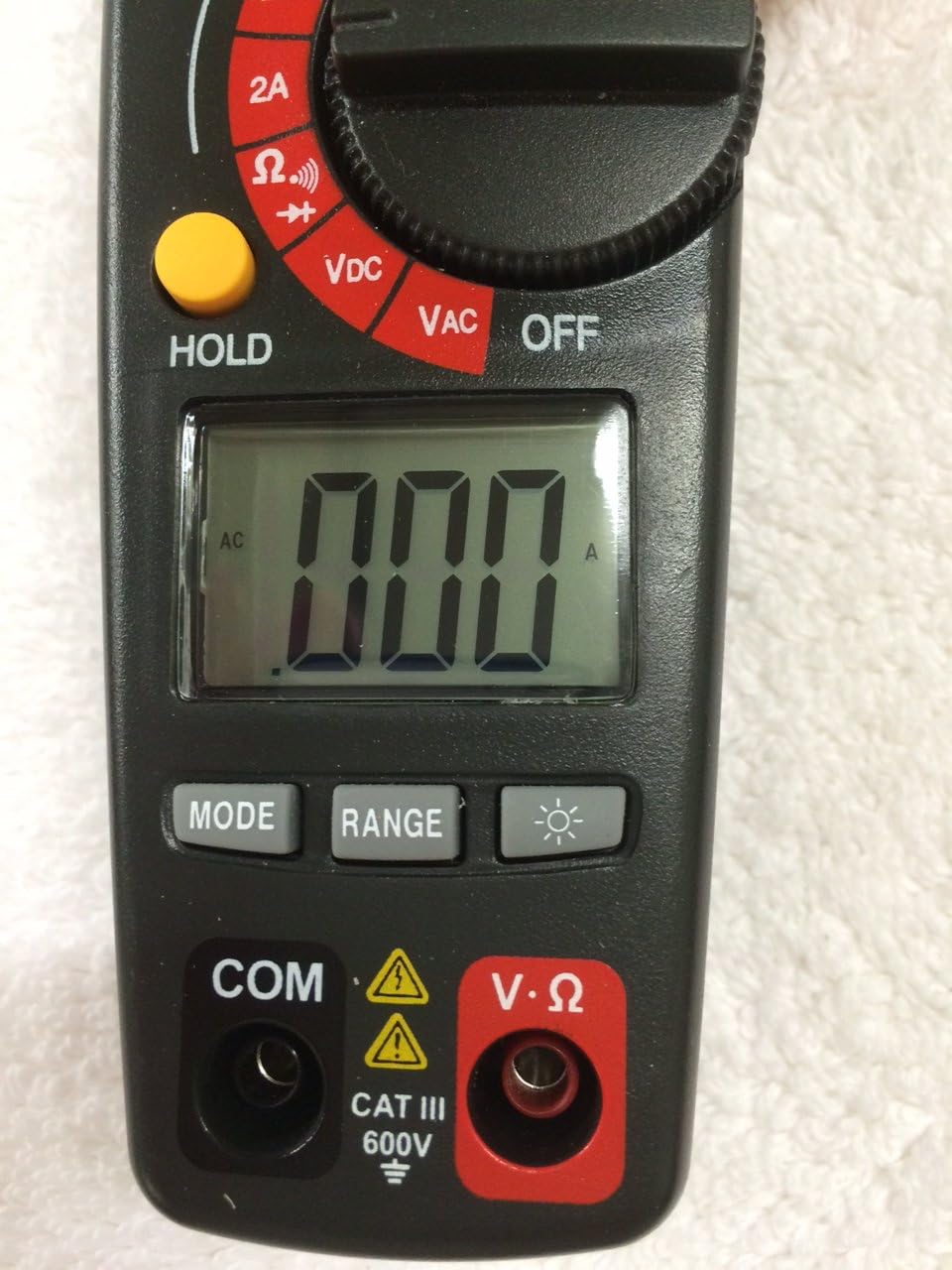
Figure 2: Bottom Section of the Ammeter
This image shows the lower part of the Craftsman Digital 400A AC Clamp-On Ammeter. Key features include the large LCD display, the 'MODE' button, 'RANGE' button, and the backlight button (indicated by a light bulb icon). Below the display are the input jacks: 'COM' (common) and 'V·Ω' (voltage/resistance) with a CAT III 600V safety rating warning.
- Clamp Jaw: Used for non-contact AC current measurements.
- Function Dial: Selects the desired measurement function (AC Current, Voltage, Resistance, etc.) and turns the meter ON/OFF.
- LCD Display: Shows measurement readings, units, and function indicators.
- MAX Button: Toggles between maximum value hold and normal operation.
- HOLD Button: Freezes the current reading on the display.
- MODE Button: Selects between different functions within a dial setting (e.g., AC/DC voltage, continuity/diode).
- RANGE Button: Manually selects measurement range or returns to auto-ranging.
- Backlight Button: Activates the display backlight for improved visibility in low light.
- Input Jacks (COM, V·Ω): For connecting test leads for voltage, resistance, continuity, diode, capacitance, and frequency measurements.
4. Setup
4.1 Battery Installation
The meter requires batteries for operation. To install or replace batteries:
- Ensure the meter is OFF and disconnect any test leads.
- Locate the battery compartment cover on the back of the meter.
- Unscrew the retaining screw(s) and remove the cover.
- Insert new batteries, observing correct polarity (+ and -).
- Replace the battery compartment cover and secure it with the screw(s).
Note: The meter features auto power off to conserve battery life.
5. Operating Instructions
Before taking any measurements, ensure the meter is in good condition and the test leads are properly connected (if applicable).
5.1 Measuring AC Current (Clamp Function)
This function allows non-contact measurement of AC current up to 400A.
- Turn the function dial to the desired AC current range (2A, 20A, 200A, or 400A).
- Press the clamp trigger to open the clamp jaw.
- Enclose a single conductor (not a bundle of wires) within the clamp jaw. Ensure the jaw is fully closed.
- Read the AC current value on the LCD display.
Note: For accurate readings, ensure only one conductor is inside the clamp jaw.
5.2 Measuring AC/DC Voltage
The meter measures AC/DC voltage up to 600V.
- Insert the black test lead into the COM jack and the red test lead into the V·Ω jack.
- Turn the function dial to the VDC or VAC position.
- If measuring DC voltage, press the MODE button to select DC if necessary.
- Connect the test probes across the circuit or component to be measured.
- Read the voltage value on the LCD display.
5.3 Measuring Resistance (Ω)
Measures resistance in Ohms (Ω).
- Insert the black test lead into the COM jack and the red test lead into the V·Ω jack.
- Turn the function dial to the Ω position.
- Ensure the circuit or component is de-energized before measuring resistance.
- Connect the test probes across the component.
- Read the resistance value on the LCD display.
5.4 Continuity and Diode Test
These functions are typically accessed via the Ω setting using the MODE button.
- Insert the black test lead into the COM jack and the red test lead into the V·Ω jack.
- Turn the function dial to the Ω position.
- Press the MODE button repeatedly until the continuity symbol (a speaker icon) or diode symbol (a triangle with a line) appears on the display.
- For continuity: Connect probes across the circuit. A continuous beep indicates a complete circuit.
- For diode: Connect probes across the diode. A forward bias voltage drop will be displayed. Reverse bias should show OL (open loop).
5.5 Measuring Frequency and Capacitance
The meter supports frequency and capacitance measurements, typically accessed through the V·Ω input and MODE button.
- Insert the black test lead into the COM jack and the red test lead into the V·Ω jack.
- Turn the function dial to the appropriate setting (often shared with voltage or resistance, requiring MODE selection).
- Press the MODE button until the frequency (Hz) or capacitance (F) symbol appears.
- Connect the test probes to the circuit or component.
- Read the value on the LCD display.
5.6 Temperature Measurement (Type K Thermometer)
The meter includes a Type K thermometer for surface or air temperature measurements.
- Ensure the meter is OFF and disconnect any test leads.
- Insert the Type K thermocouple probe into the designated input jacks (usually marked with 'TEMP' or shared with V·Ω, check meter markings).
- Turn the function dial to the temperature setting (often marked with °C or °F).
- Place the thermocouple tip on or near the object whose temperature is to be measured.
- Read the temperature on the LCD display.
5.7 Data Hold and Max Hold
- HOLD Button: Press the HOLD button to freeze the current reading on the display. Press again to release.
- MAX Button: Press the MAX button to capture and display the maximum measured value. Press again to exit MAX hold.
6. Maintenance
6.1 Cleaning
Wipe the meter with a damp cloth and mild detergent. Do not use abrasives or solvents. Keep the clamp jaw free of dust and debris.
6.2 Battery Replacement
Refer to Section 4.1 for battery installation/replacement instructions. Replace batteries when the low battery indicator appears on the display to ensure accurate readings.
6.3 Storage
If the meter is not used for an extended period, remove the batteries to prevent leakage. Store the meter in a cool, dry place away from direct sunlight.
7. Troubleshooting
| Problem | Possible Cause | Solution |
|---|---|---|
| Meter does not turn on. | Dead or incorrectly installed batteries. | Check battery polarity; replace batteries. |
| "OL" (Overload) displayed. | Measurement exceeds selected range or meter's maximum capacity. | Select a higher range or ensure measurement is within meter's specifications. |
| Inaccurate readings. | Low battery, incorrect function/range, poor test lead connection, external interference. | Replace batteries, verify function/range, ensure secure connections, move away from strong magnetic fields. |
| No reading for AC current. | Multiple conductors in clamp jaw, DC current being measured. | Ensure only one AC conductor is in the clamp. This meter measures AC current only. |
8. Specifications
| Feature | Specification |
|---|---|
| Brand | Craftsman |
| Model | 82372 |
| Measurement Type | Ammeter (Clamp-On) |
| AC Current Range | Up to 400A |
| AC/DC Voltage Range | Up to 600V |
| Resistance | Yes |
| Frequency | Yes |
| Capacitance | Yes |
| Continuity Test | Yes |
| Diode Test | Yes |
| Temperature Measurement | Type K Thermometer |
| Display | 4000 Count LCD |
| Accuracy (AC Current) | 3.0% (VAC) - Note: Product description states 3.0% (VAC) for AC/DC current, which is unusual. Assuming it refers to AC current accuracy. |
| Safety Rating | Category III - 600V |
| Power Source | Battery Powered |
| Special Features | One-touch auto zero, belt holster, molded rubber holster, auto on/off, Data Hold, Max Hold. |
9. Warranty and Support
For warranty information and technical support, please refer to the official Craftsman website or contact their customer service. Keep your purchase receipt as proof of purchase for any warranty claims.
Craftsman Customer Service: Please visit www.craftsman.com/support for the latest support information and contact details.


