
1. Introduction
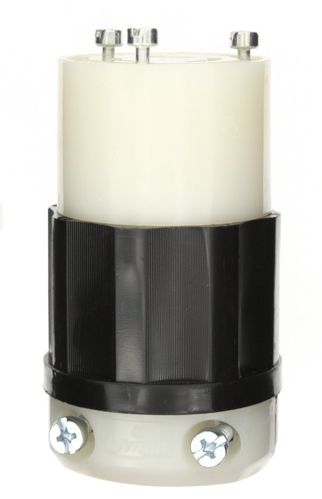
This manual provides detailed instructions for the safe and proper installation and use of the Leviton 7314-GC 20 Amp, 125/250 Volt, Industrial Grade, Grounding, Locking Connector. This polarized connector features an impact-modified nylon material, a black and white color scheme, and a non-NEMA configuration. It is designed for 3-wire applications and is UL 498 and CSA C22.2 approved. The connector is rated for 125/250 VAC voltage and 20 amperes current, with grounding capabilities and 3 poles. It accommodates a cord size ranging from 0.385 to 0.78 inches.
2. Important Safety Information
WARNING: Shock Hazard. To avoid risk of serious injury or death, turn power off at the circuit breaker before wiring any electrical device. Always ensure power is disconnected before beginning installation or maintenance.
- Always disconnect power at the circuit breaker or fuse box before installing or servicing the connector.
- Ensure all wiring connections are secure and properly insulated.
- Use appropriate tools for installation.
- Verify the voltage and amperage ratings of the connector match your application requirements.
- If you are unsure about any part of these instructions, consult a qualified electrician.
3. Product Overview
The Leviton 7314-GC Locking Connector is engineered for superior performance and long-lasting reliability in industrial applications. Key features include:
- 20A 125/250V LKG CONN GRND: Designed for robust electrical connections.
- Molded-in strip gauge: Facilitates fast, accurate wire stripping.
- Terminal identification letters: Located on the back cover for quick and accurate termination.
- Contact Material: Made from durable Copper-Alloy for optimal conductivity.
4. Setup and Wiring Instructions
Follow these steps to properly wire your Leviton locking connector. Refer to the accompanying video for a visual guide.
Video demonstrating the wiring process for Leviton Black and White Plugs and Connectors.
- Prepare for Wiring: Before wiring, ensure the power to the cable is completely off at the circuit breaker. Identify the NEMA configuration, amperage, and voltage stamped on the connector's faceplate.
- Disassemble the Connector: Using a Phillips head screwdriver, loosen the quick screws on the faceplate and carefully remove the faceplate from the body housing.
- Prepare the Strain Relief: Loosen the two strain relief screws on the strain relief component.
- Feed the Cable: Take your cable and feed it through the loosened strain relief and then through the body housing.
- Strip the Cord Jacket: Strip approximately 1.5 inches of the cord jacket according to the diagram provided on the instruction sheet (if applicable).
- Trim the Ground Wire: Your green (ground) wire will need to be cut to be approximately 1 inch long. Use wire strippers to cut the wire.
- Strip Individual Wires: Strip approximately 5/8 of an inch from the ends of all individual wires (hot, neutral, and ground).
- Loosen Terminal Screws: Take the faceplate and loosen all terminal screws. The green ground screw is typically in the center of the device. Back out the screws fully.
- Connect the Ground Wire: Insert the green (ground) wire into the wire well of the green (ground) terminal screw. Push it in fully, then tighten the terminal screw with a Phillips screwdriver.
- Connect the Neutral Wire: Insert the white (neutral) wire into the wire well of the silver terminal screw. Push it in fully, then tighten the terminal screw.
- Connect Hot Wires: Connect the remaining hot wires (e.g., black, red, orange) into the wire wells of the brass terminals. Insert them fully and then tighten each terminal screw.
- Reassemble the Connector: Slide the faceplate back into the body housing. Note the channel guide on the body housing that aligns perfectly with the faceplate to ensure correct orientation.
- Secure the Faceplate: Using a Phillips head screwdriver, tighten the quick screws on the faceplate to secure it to the body housing.
- Tighten Strain Relief: As the final step, tighten both screws on the strain relief to secure the cable. If your wire is larger than the groove on the strain relief, you may remove a section of the strain relief to accommodate the larger wire.
5. Operating Instructions
Once the Leviton 7314-GC locking connector is properly wired to your cable, it is ready for use. To operate:
- Ensure the power source is off before making any connections.
- Align the pins of the 7314-GC connector with the corresponding slots of a compatible locking receptacle or plug.
- Insert the connector fully and twist clockwise to lock it into place. This ensures a secure and reliable electrical connection.
- Once locked, you may restore power to the circuit.
- To disconnect, turn off the power, twist counter-clockwise to unlock, and pull the connector straight out.
6. Maintenance
Regular maintenance helps ensure the longevity and safe operation of your Leviton 7314-GC connector.
- Periodic Inspection: Regularly inspect the connector for any signs of wear, damage, cracks, or discoloration. Check the cable entry point for fraying or damage to the outer jacket.
- Connection Integrity: Periodically check that the quick screws on the faceplate and the strain relief screws are tight. Loose connections can lead to overheating and potential hazards.
- Cleaning: If necessary, clean the exterior of the connector with a dry, lint-free cloth. Do not use abrasive cleaners or solvents. Ensure the connector is disconnected from power before cleaning.
- Storage: When not in use, store the connector in a clean, dry environment, away from extreme temperatures and direct sunlight.
- Replacement: If any part of the connector shows significant wear or damage, replace the unit immediately. Do not attempt to repair damaged electrical components.
7. Troubleshooting
If you encounter issues with your Leviton 7314-GC connector, consider the following common troubleshooting steps:
- No Power:
- Verify that power is supplied to the circuit at the breaker or fuse box.
- Check all wire connections within the connector to ensure they are secure and properly terminated.
- Inspect the cable for any cuts, breaks, or damage.
- Loose Connection:
- Ensure the connector is fully inserted and twisted clockwise into the receptacle/plug.
- Check the terminal screws inside the connector for tightness.
- Verify the strain relief is securely tightened around the cable.
- Overheating:
- Immediately disconnect power.
- Overheating can indicate loose connections or an overloaded circuit. Recheck all wiring and ensure the load does not exceed the connector's 20 Amp rating.
- If overheating persists, discontinue use and consult a qualified electrician.
8. Specifications
| Feature | Specification |
|---|---|
| Model Number | 7314-GC |
| Brand | Leviton |
| Amperage | 20 Amps |
| Voltage | 125/250 Volts AC |
| Number of Poles | 3 |
| Number of Wires | 3 |
| Plug Format | Type D (Non-NEMA Configuration) |
| Product Grade | Industrial |
| Material | Impact Modified Nylon |
| Cord Size Range | 0.385 to 0.78 inches |
| Approvals | UL 498, CSA C22.2 |
| Item Weight | 5.6 ounces |
| Product Dimensions | 2 x 4 x 2 inches |
9. Warranty and Support
This Leviton product is backed by a manufacturer's warranty. For specific details regarding the warranty period and coverage, please refer to the documentation included with your purchase or visit the official Leviton website.
Customer Support
For technical assistance, troubleshooting, or product inquiries, please contact Leviton Customer Support:
- Website: Visit www.leviton.com for FAQs, product information, and support resources.
- Phone: Refer to the Leviton website for regional customer service contact numbers.