1. Introduction
Thank you for choosing the Voltcraft VC-11 Digital Multimeter. This portable, Category III, 250V multimeter with a 2000-count display is designed for accurate electrical measurements in various applications. This manual provides essential information for safe operation, proper use, and maintenance of your device. Please read it thoroughly before use and keep it for future reference.
2. Safety Information
WARNING: Electrical shock hazard. Improper use of this meter can cause damage, shock, injury, or death. Read and understand this manual before operating the meter.
- Always ensure the meter is in good working condition and the test leads are not damaged.
- Do not apply more than the rated voltage, as marked on the meter, between terminals or between any terminal and ground.
- Use extreme caution when working with voltages above 25V AC RMS or 35V DC. These voltages pose a shock hazard.
- Always disconnect the test leads from the circuit before changing functions or ranges.
- Do not operate the meter with the battery cover removed or loosened.
- Adhere to local and national safety codes. Use personal protective equipment (PPE) such as approved safety glasses and electrically insulated gloves.
3. Product Overview
The Voltcraft VC-11 is a compact digital multimeter featuring a clear LCD display, a rotary function switch, and input jacks for test leads. It is designed for measuring DC/AC voltage, DC current, resistance, and includes diode and continuity test functions.
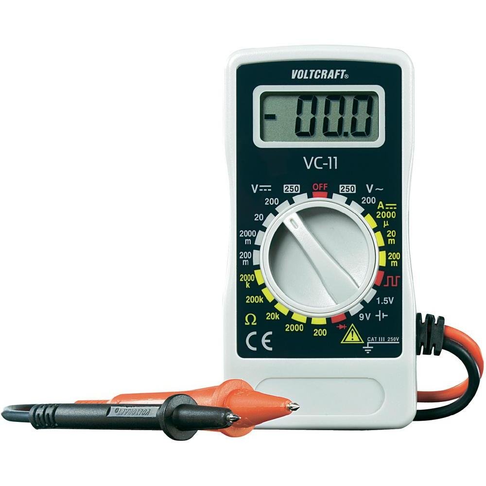
Figure 1: Front view of the Voltcraft VC-11 Digital Multimeter with test leads connected. This image shows the LCD display, rotary switch, and input terminals.

Figure 2: Angled view of the Voltcraft VC-11 Digital Multimeter, highlighting the compact design and the CE marking.

Figure 3: The Voltcraft VC-11 Digital Multimeter shown with its test leads detached, illustrating the input ports.
3.1 Components
- LCD Display: Shows measurement readings, units, and function indicators.
- Rotary Switch: Used to select measurement functions and ranges.
- Input Jacks: Ports for connecting the test leads (COM, VΩmA).
- Test Leads: Red and black leads for connecting to the circuit under test.
4. Setup
4.1 Battery Installation
The Voltcraft VC-11 requires a 9V battery for operation (not included). To install or replace the battery:
- Ensure the multimeter is turned OFF and disconnect all test leads.
- Locate the battery compartment cover on the back of the meter.
- Use a screwdriver to remove the screw securing the battery cover.
- Carefully remove the cover.
- Connect a new 9V battery to the battery clip, observing correct polarity.
- Place the battery into the compartment and replace the cover, securing it with the screw.
4.2 Connecting Test Leads
Always connect the black test lead to the 'COM' (common) jack. Connect the red test lead to the appropriate input jack based on the desired measurement:
- For Voltage (V), Resistance (Ω), Diode, and Continuity measurements, connect the red lead to the 'VΩmA' jack.
- For Current (A) measurements, connect the red lead to the 'VΩmA' jack (for mA range).
5. Operating Instructions
Before taking any measurement, ensure the test leads are correctly connected and the rotary switch is set to the desired function and range.
5.1 Measuring DC Voltage (V=)
- Set the rotary switch to the desired DC Voltage (V=) range (e.g., 200mV, 2V, 20V, 200V, 250V). If the voltage is unknown, start with the highest range and decrease as needed.
- Connect the black test lead to the 'COM' jack and the red test lead to the 'VΩmA' jack.
- Connect the test probes in parallel across the component or circuit to be measured.
- Read the voltage value on the LCD display.
5.2 Measuring AC Voltage (V~)
- Set the rotary switch to the desired AC Voltage (V~) range (e.g., 200V, 250V).
- Connect the black test lead to the 'COM' jack and the red test lead to the 'VΩmA' jack.
- Connect the test probes in parallel across the AC source or component.
- Read the voltage value on the LCD display.
5.3 Measuring DC Current (A=)
- Set the rotary switch to the desired DC Current (A=) range (e.g., 2000µA, 20mA, 200mA).
- Connect the black test lead to the 'COM' jack and the red test lead to the 'VΩmA' jack.
- WARNING: To measure current, the meter must be connected in series with the circuit. Break the circuit and insert the meter.
- Connect the test probes in series with the circuit.
- Read the current value on the LCD display.
5.4 Measuring Resistance (Ω)
- Ensure the circuit is de-energized before measuring resistance.
- Set the rotary switch to the desired Resistance (Ω) range (e.g., 200Ω, 2kΩ, 20kΩ, 200kΩ, 2000kΩ).
- Connect the black test lead to the 'COM' jack and the red test lead to the 'VΩmA' jack.
- Connect the test probes across the component to be measured.
- Read the resistance value on the LCD display.
5.5 Diode Test
- Ensure the circuit is de-energized.
- Set the rotary switch to the Diode symbol (usually next to resistance).
- Connect the black test lead to the 'COM' jack and the red test lead to the 'VΩmA' jack.
- Connect the red probe to the anode and the black probe to the cathode of the diode. The display will show the forward voltage drop.
- Reverse the probes. The display should show 'OL' (Overload) for a good diode.
5.6 Continuity Test
- Ensure the circuit is de-energized.
- Set the rotary switch to the Continuity symbol (usually next to diode/resistance).
- Connect the black test lead to the 'COM' jack and the red test lead to the 'VΩmA' jack.
- Connect the test probes across the circuit or component.
- If the resistance is below a certain threshold (typically 30-50Ω), the meter will emit an audible beep, indicating continuity.
6. Maintenance
6.1 Cleaning
Wipe the meter with a damp cloth and a mild detergent. Do not use abrasives or solvents. Ensure the meter is completely dry before use.
6.2 Battery Replacement
When the battery symbol appears on the LCD display, the 9V battery needs to be replaced. Refer to section 4.1 for battery installation instructions.
7. Troubleshooting
| Problem | Possible Cause | Solution |
|---|---|---|
| No display or dim display | Dead or low battery | Replace the 9V battery. |
| Incorrect readings | Incorrect function/range selected Poor test lead connection Damaged test leads | Select the correct function and range. Ensure test leads are firmly connected. Inspect and replace damaged test leads. |
| "OL" (Overload) displayed | Measurement exceeds selected range Open circuit (for resistance/current) | Select a higher range. Check for breaks in the circuit. |
8. Specifications
- Brand: VOLTCRAFT
- Model Number: VC11
- Manufacturer: VOLTCRAFT
- Product Weight: Approximately 9.07 g (without packaging)
- Package Dimensions: 14.8 x 8 x 3.6 cm
- Category Rating: CAT III 250V
- Display: 2000 Counts
- Power Source: 9V Battery (not included)
9. Warranty Information
This product is covered by a standard manufacturer's warranty. Please refer to the warranty card included with your purchase or contact your retailer for specific terms and conditions. The warranty typically covers defects in materials and workmanship under normal use.
10. Customer Support
For technical assistance, troubleshooting, or service inquiries, please contact Voltcraft customer support or your local distributor. Contact information can usually be found on the manufacturer's website or on the product packaging.


