1. Introduction
This manual provides detailed instructions for the installation, configuration, and maintenance of your ASRock G41C-VS motherboard. Please read this manual thoroughly before installing the motherboard to ensure proper setup and operation. This motherboard supports Intel Core 2 Extreme, Core 2 Quad, Core 2 Duo, Pentium Dual Core, and Celeron processors with an LGA 775 socket, and features both DDR2 and DDR3 memory support.
2. Setup and Installation
2.1 Motherboard Layout
Familiarize yourself with the components and connectors on the motherboard before proceeding with installation.
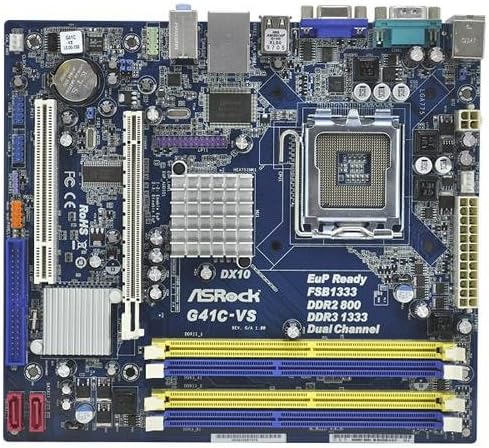
Image 1: Overview of the ASRock G41C-VS motherboard, showing the CPU socket, memory slots, expansion slots, and various connectors.
2.2 Processor (CPU) Installation
The ASRock G41C-VS motherboard uses an LGA 775 socket. Follow these steps to install your compatible Intel processor:
- Locate the LGA 775 CPU socket on the motherboard.
- Gently push down the load lever and pull it to the side to open the socket retention frame.
- Carefully align the CPU with the socket, ensuring the golden triangle on the CPU matches the triangle on the socket. Do not force the CPU into the socket.
- Lower the CPU into the socket.
- Close the retention frame and secure it by pushing the load lever back into its locked position.
- Apply a thin layer of thermal paste to the CPU surface, then install the CPU cooler according to its manufacturer's instructions.
2.3 Memory (RAM) Installation
This motherboard supports both DDR2 and DDR3 memory modules. It features two DDR2 DIMM slots and two DDR3 DIMM slots, supporting dual channel memory architecture.
- Open the clips at both ends of the DIMM slot.
- Align the memory module with the slot, ensuring the notch on the module matches the key in the slot.
- Press down firmly on both ends of the memory module until the clips snap into place.
- Ensure both clips are fully closed and the module is securely seated.
2.4 Expansion Card Installation
The motherboard includes one PCI-Express x16 slot for graphics cards and one PCI slot for other expansion cards.
- Locate the desired expansion slot.
- Remove the corresponding metal bracket from your PC case.
- Align the expansion card with the slot and press down firmly until it is fully seated.
- Secure the card with a screw to the PC case.
2.5 Connecting Peripherals and Power
Connect all necessary cables to the motherboard:
- Power Connectors: Connect the 24-pin ATX power connector and the 4-pin ATX 12V power connector from your power supply unit (PSU) to the motherboard.
- SATA Devices: Connect your SATA hard drives or SSDs to the SATA ports on the motherboard using the provided SATA data cables.
- Front Panel Connectors: Connect the power switch, reset switch, power LED, and HDD LED cables from your PC case to the front panel header on the motherboard. Refer to the motherboard diagram for correct pin assignments.
- USB Ports: Connect internal USB headers for front panel USB ports. Connect external USB devices to the rear USB 2.0 ports.
- Audio: Connect front panel audio cables to the appropriate header. Connect speakers or headphones to the rear audio jacks.
- Video: Connect your monitor to the VGA port on the rear I/O panel if using integrated graphics.
- Network: Connect an Ethernet cable to the RJ45 LAN port for network access.
3. Operating Instructions
3.1 Initial Boot and BIOS Setup
After completing hardware installation, power on your system. During the initial boot sequence, you can access the BIOS (Basic Input/Output System) setup utility by pressing the DEL key (or as indicated on screen).
- BIOS Settings: Configure boot order, date and time, and other system parameters as needed. Save changes before exiting the BIOS.
- Operating System Installation: Install your preferred operating system from a bootable USB drive or optical disc.
3.2 Driver Installation
For optimal performance and stability, install the necessary drivers for your motherboard components. These drivers can be found on the included support CD or downloaded from the official ASRock website.
- Install chipset drivers.
- Install integrated graphics drivers (Intel GMA X4500).
- Install audio drivers.
- Install LAN drivers.
4. Maintenance
4.1 Cleaning
Regularly clean your computer's interior to prevent dust buildup, which can lead to overheating and component failure. Use compressed air to remove dust from fans, heatsinks, and other components. Ensure the system is powered off and unplugged before cleaning.
4.2 CMOS Battery Replacement
The motherboard uses a CR2032 lithium coin cell battery to power the CMOS (Complementary Metal-Oxide-Semiconductor) memory, which stores BIOS settings and the system clock. If your system consistently loses time or BIOS settings, the battery may need replacement. Locate the battery holder on the motherboard, gently remove the old battery, and insert a new CR2032 battery with the positive (+) side facing up.
5. Troubleshooting
This section provides solutions to common issues you might encounter.
- No Power: Ensure all power cables (24-pin ATX, 4-pin ATX 12V) are securely connected to the motherboard and PSU. Verify the PSU is switched on and connected to a working power outlet.
- No Display: Check that the monitor is properly connected to the VGA port. If using a discrete graphics card, ensure it is correctly seated in the PCI-Express x16 slot and connected to power (if required). Try reseating RAM modules.
- System Instability/Crashes: This can be caused by improperly seated RAM, overheating, or outdated drivers. Ensure RAM is correctly installed, CPU cooler is functioning, and all drivers are up-to-date.
- CMOS Reset: If you encounter issues after changing BIOS settings, you can reset the CMOS to default settings. This is typically done by briefly shorting a specific jumper on the motherboard (refer to the motherboard diagram for the CLRCMOS1 jumper) or by removing the CMOS battery for a few minutes.
6. Specifications
Below are the technical specifications for the ASRock G41C-VS motherboard:
| Component | Specification |
|---|---|
| Processor Support | LGA 775 for Intel Core 2 Extreme, Core 2 Quad, Core 2 Duo, Pentium Dual Core, Celeron Processors |
| Chipset | Intel G41 + ICH7 |
| Memory | 2 x DDR2 DIMM slots (DDR2 800/667 non-ECC, un-buffered, max 8GB) 2 x DDR3 DIMM slots (DDR3 1333(OC)/1066/800 non-ECC, un-buffered, max 8GB) Supports Dual Channel Memory Technology |
| Expansion Slots | 1 x PCI Express x16 slot 1 x PCI slot |
| Graphics | Integrated Intel GMA X4500 Graphics Max. shared memory 1759MB Supports DirectX 10, Pixel Shader 4.0 |
| Storage | 4 x SATA2 3.0 Gb/s connectors |
| Audio | 5.1 CH HD Audio (VIA VT1705 Audio Codec) |
| LAN | PCIE x1 Gigabit LAN 10/100/1000 Mb/s (Realtek RTL8111DL) |
| Rear Panel I/O | 1 x PS/2 Mouse Port 1 x PS/2 Keyboard Port 1 x Serial Port: COM1 1 x VGA Port 4 x USB 2.0 Ports 1 x RJ-45 LAN Port with LED HD Audio Jacks: Line in / Front Speaker / Microphone |
| Internal Connectors | 2 x USB 2.0 Headers (support 4 USB 2.0 ports) 1 x CPU Fan Connector 1 x Chassis Fan Connector 1 x 24 pin ATX Power Connector 1 x 4 pin 12V Power Connector 1 x Front Panel Audio Connector 1 x SPDIF Out Header 1 x Clear CMOS Jumper |
| Form Factor | Micro ATX Form Factor (8.9-in x 7.5-in, 22.6 cm x 19.1 cm) |
| Product Dimensions | 8.8 x 7.8 x 1.9 inches |
| Item Weight | 1.81 pounds |
7. Package Contents
The ASRock G41C-VS motherboard package typically includes the following items:
- ASRock G41C-VS Motherboard
- Quick Installation Guide
- Support CD (for drivers and utilities)
- I/O Shield
- 2 x SATA Data Cables
8. Support and Warranty
For technical support, driver updates, and further information, please visit the official ASRock website. Warranty terms and conditions are subject to regional policies and can be found on the ASRock support page or by contacting your local retailer.
For additional assistance, you may refer to the ASRock support resources available online.


