1. Introduction
This manual provides detailed instructions for the installation, operation, and maintenance of your BOSS Audio Systems NX2500.4 Onyx 4-Channel MOSFET Bridgeable Amplifier. Please read this manual thoroughly before attempting installation or operation to ensure proper use and to prevent damage to the unit or your vehicle's audio system.
The NX2500.4 amplifier is designed to deliver high-quality audio performance with versatile configuration options, including 4-channel and bridged modes, making it suitable for various car audio setups.
2. Key Features
- Four-Channel/Bridged Mode: Operates in 4-channel mode (625 Watts x 4 peak at 2 ohms; 250 Watts x 4 at 4 ohms) or bridged mode (1250 Watts x 2 peak at 4 ohms).
- MOSFET Power Supply: Ensures high performance with efficient power delivery and low heat generation.
- Variable Gain Controls: Allows matching the input gain to your receiver for optimal sound quality and reduced distortion.
- Remote Subwoofer Level Control: Included for convenient adjustment of subwoofer output levels when connected.
- Full Range Crossovers: Features variable high-pass and low-pass crossovers for precise audio tuning and speaker protection.
- Line/Speaker Level Inputs: Accommodates both RCA line-level inputs and speaker-level inputs for compatibility with various head units.
- Bass Boost: Adjustable bass boost (0 to +18dB) for enhanced low-frequency response.
- Tri-mode Operation: Supports sending signals to a tri-way crossover for integrating a subwoofer with front/rear two-channel outputs.
- Power and Protection LEDs: Indicators for operational status and fault conditions.
3. Package Contents
Verify that all items are present in the package:
- BOSS NX2500.4 Amplifier
- Remote Subwoofer Level Control
- User's Manual (this document)
4. Installation and Setup
Proper installation is crucial for optimal performance and safety. If you are unsure about any part of the installation process, consult a professional installer.
4.1 Safety Precautions
- Disconnect the vehicle's negative battery terminal before starting any wiring.
- Ensure all wiring is securely connected and properly insulated to prevent short circuits.
- Mount the amplifier in a location that allows for adequate ventilation and is protected from moisture and excessive heat.
- Use appropriate gauge wiring for power, ground, and speaker connections as specified.
4.2 Wiring Connections Overview
The following image illustrates the general layout of the amplifier and its connection points. Refer to this for visual guidance during installation.
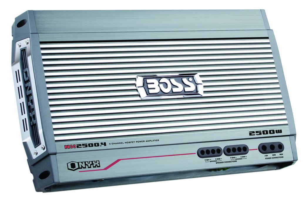
An image showing the BOSS Audio Systems NX2500.4 Onyx 4-Channel Amplifier, highlighting its compact design and connection terminals for power, ground, remote, inputs, and outputs.
4.3 Power Connection (BATT+)
Connect a heavy-gauge wire directly from the positive (+) terminal of the vehicle's battery to the BATT+ terminal on the amplifier. An in-line fuse holder with a fuse of appropriate rating (not supplied) must be installed within 18 inches (45 cm) of the battery.
4.4 Ground Connection (GND)
Connect a heavy-gauge wire from the GND terminal on the amplifier to a clean, unpainted metal surface on the vehicle's chassis. Ensure a good electrical connection by scraping away any paint or rust from the contact point.
4.5 Remote Turn-On (REM)
Connect a smaller gauge wire from the REM terminal on the amplifier to the remote turn-on output of your head unit. This wire signals the amplifier to turn on when the head unit is activated.
4.6 Audio Input Connection
- RCA Inputs: If your head unit has RCA pre-amp outputs, connect RCA cables from the head unit to the amplifier's RCA INPUT terminals.
- Speaker Level Inputs: If your head unit lacks RCA outputs, use the speaker-level inputs. Connect the speaker wires from your head unit's speaker outputs to the amplifier's high-level input connector (if provided).
4.7 Speaker Output Connection
Connect your speakers to the amplifier's speaker output terminals. Observe correct polarity (+ to + and – to –). The NX2500.4 supports various configurations:
- 4-Channel Mode: Connect four speakers, one to each channel output.
- Bridged Mode: Connect two speakers (e.g., subwoofers) by bridging two channels together. Refer to the amplifier's terminal markings for correct bridging connections.
- Trimode Operation: Allows for a combination of stereo speakers and a subwoofer. Consult a wiring diagram for specific trimode connections.
5. Operation
Once installed, adjust the amplifier settings for optimal sound performance.
5.1 Gain Control
The variable gain control (often labeled 'Input Level' or 'Gain') matches the amplifier's input sensitivity to the output level of your head unit. Start with the gain set to minimum, then slowly increase it until you achieve a clear, undistorted sound at your desired volume level from the head unit.
5.2 Crossover Settings
The NX2500.4 features variable high-pass (HPF) and low-pass (LPF) crossovers:
- High-Pass Filter (HPF): Allows frequencies above the set point to pass through, blocking lower frequencies. Use for full-range speakers to prevent distortion from bass frequencies.
- Low-Pass Filter (LPF): Allows frequencies below the set point to pass through, blocking higher frequencies. Use for subwoofers to ensure they only reproduce bass.
Adjust these settings based on the frequency response of your speakers and subwoofers to achieve a balanced sound.
5.3 Bass Boost
The variable bass boost control (0 to +18dB) allows you to enhance the low-end frequencies. Use this feature sparingly to avoid distortion and potential speaker damage. Adjust to your preference for added bass impact.
5.4 Remote Subwoofer Level Control
If a subwoofer is connected to the amplifier, the included remote level control allows for convenient, on-the-fly adjustments of the subwoofer's output level from the driver's seat.
5.5 Operating Modes
The amplifier can be configured for different operating modes:
- 4-Channel Stereo: For driving four full-range speakers.
- 2-Channel Bridged: For driving two subwoofers or high-power speakers.
- Tri-mode: A combination of 2-channel stereo and 1-channel bridged for a subwoofer.
Ensure the correct mode is selected via any switches on the amplifier and that wiring corresponds to the chosen mode.
6. Maintenance
Regular maintenance helps ensure the longevity and performance of your amplifier.
- Cleaning: Periodically wipe the amplifier's exterior with a soft, dry cloth. Avoid using harsh chemicals or abrasive cleaners.
- Ventilation: Ensure that the amplifier's cooling fins are free from dust and obstructions to maintain proper airflow.
- Connections: Occasionally check all power, ground, and speaker connections to ensure they are secure and free from corrosion.
7. Troubleshooting
If you experience issues with your amplifier, refer to the following common problems and solutions.
7.1 Protection LED Indicator
The amplifier is equipped with protection circuitry. If the protection LED illuminates, the amplifier has detected a fault and has shut down to prevent damage. Common causes include:
- Overheating: Ensure adequate ventilation around the amplifier. Allow it to cool down.
- Short Circuit: Check speaker wiring for shorts to ground or between positive and negative terminals.
- Low Impedance: Ensure the total impedance of connected speakers meets the amplifier's specifications.
- DC Offset: A fault within the amplifier itself.
After resolving the issue, turn the vehicle's ignition off and then on again to reset the amplifier.
7.2 No Sound
- Check power, ground, and remote turn-on connections.
- Verify RCA or speaker-level input connections from the head unit.
- Ensure the head unit is on and functioning correctly.
- Check speaker wires for proper connection and continuity.
7.3 Distortion
- Adjust the amplifier's gain control to prevent clipping.
- Check speaker impedance and ensure it is within the amplifier's acceptable range.
- Verify that the head unit's output is not distorted.
- Adjust crossover settings to prevent speakers from playing frequencies they cannot handle.
8. Technical Specifications
| Specification | Value |
|---|---|
| Model Number | NX2500.4 |
| Output Power (Peak) | 2500 Watts |
| Number of Channels | 4 |
| 4-Channel Mode (2 Ohms) | 625 Watts x 4 |
| 4-Channel Mode (4 Ohms) | 250 Watts x 4 |
| Bridged Mode (4 Ohms) | 1250 Watts x 2 |
| Power Supply Type | MOSFET |
| Voltage | 12 Volts (DC) |
| Item Dimensions (L x W x H) | 18.3 x 2.38 x 10 inches |
| Item Weight | 12.6 pounds |
| Mounting Type | Surface Mount |
| UPC | 791489113762 |
9. Warranty Information
The BOSS Audio Systems NX2500.4 amplifier comes with a SIX-YEAR warranty. Please retain your proof of purchase for warranty claims. The warranty covers defects in materials and workmanship under normal use. It does not cover damage caused by improper installation, accident, misuse, abuse, neglect, or unauthorized modification.
10. Customer Support
If you have further questions or require technical assistance that is not covered in this manual, please contact BOSS Audio Systems customer support. Before contacting support, ensure you have reviewed this manual and performed basic troubleshooting steps.


