1. Introduction
This manual provides essential information for the safe operation, assembly, maintenance, and troubleshooting of your JET J-2500 15-Inch Floor Drill Press. The JET J-2500 is designed for precision drilling tasks, offering accuracy, stability, and versatility. It features a 3/4 HP motor, 16 spindle speeds, and a robust cast iron construction.
Please read this manual thoroughly before operating the machine to ensure proper usage and to prevent injury or damage.
2. Safety Information
WARNING: Failure to follow these safety instructions may result in serious injury or death.
- Always wear appropriate personal protective equipment (PPE), including safety glasses, hearing protection, and dust masks when operating the drill press.
- Ensure the work area is clean, well-lit, and free from obstructions.
- Do not operate the machine in damp or wet conditions.
- Keep children and unauthorized personnel away from the operating area.
- Securely clamp all workpieces before drilling to prevent movement.
- Never wear loose clothing, gloves, or jewelry that could become entangled in moving parts.
- Disconnect power before making adjustments, changing bits, or performing maintenance.
- Use the correct drill bit for the material and task.
- Do not force the drill. Allow the machine to work at its intended speed.
- Maintain the machine in good working order. Inspect for damaged parts before each use.
3. Components Overview
The JET J-2500 Floor Drill Press consists of several key components designed for efficient and precise drilling operations.

Figure 3.1: Labeled diagram illustrating the main components of the JET J-2500 Drill Press, including the cast iron head, 3/4 HP motor, 3-1/8 inch stroke, telescoping spindle guard, 11-1/2 inch x 11-1/2 inch work table, and 2-7/8 inch ground steel column.
- Head Assembly: Houses the motor, spindle, and speed adjustment mechanism. Constructed from cast iron for durability and stability.
- Motor: A 3/4 HP motor powers the spindle, providing a speed range of 200-3,630 RPM.
- Spindle: The rotating shaft that holds the drill chuck. Features a 3-1/8 inch stroke for deep hole applications. The enclosed spindle assembly is supported by four permanently-lubricated ball bearings for precision.
- Telescoping Safety Spindle Guard: Provides protection during operation.
- Work Table: An 11-1/2 inch x 11-1/2 inch tilting table for supporting workpieces.
- Column: A large, ground steel column (2-7/8 inch diameter) provides maximum support for the head and table.
- Base: A solid cast iron base ensures stability during operation.
- Chuck: Holds drill bits up to 13mm (0.51 inches).
4. Setup and Assembly
The JET J-2500 Drill Press requires assembly before use. It is recommended to have assistance due to the weight of certain components.
4.1 Unpacking
- Carefully remove all components from the packaging.
- Verify all parts listed in the packing list are present.
- Report any missing or damaged parts to JET customer service immediately.
4.2 Assembly Steps
- Attach Column to Base: Secure the column to the base using the provided hardware. Ensure it is firmly tightened.
- Install Work Table: Slide the work table assembly onto the column. Adjust its height and secure it with the locking mechanism.
- Mount Head Assembly: With assistance, carefully lift and slide the head assembly onto the top of the column. Secure it in place according to the instructions in the detailed manual.
- Install Chuck: Clean the tapered surfaces of the spindle and chuck. Place the chuck onto the spindle taper and firmly tap it into place with a soft mallet.
- Connect Power: Ensure the drill press is connected to a suitable 115V or 230V power supply as indicated on the motor plate.
5. Operating Instructions
5.1 Power Controls

Figure 5.1: The green 'START' button initiates operation, and the red 'STOP' button halts the machine.
- To start the drill press, press the green START button.
- To stop the drill press, press the red STOP button.
5.2 Adjusting Spindle Speed
The JET J-2500 offers 16 different spindle speeds, adjustable by changing the belt position on the motor and spindle pulleys.
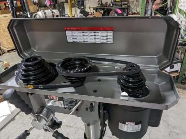
Figure 5.2: View of the belt and pulley system located under the top cover, used to adjust the spindle speed. A speed chart is typically affixed inside the cover.
- Disconnect Power: Always unplug the machine before opening the pulley cover.
- Open Pulley Cover: Lift the top cover of the head assembly.
- Consult Speed Chart: Refer to the speed chart located inside the cover to determine the correct belt configuration for your desired RPM.
- Adjust Belt Tension: Loosen the motor mount bolts to allow the motor to pivot, relieving belt tension.
- Reposition Belts: Move the belts to the appropriate pulley steps for the desired speed.
- Re-tension Belts: Apply tension to the belts by moving the motor, then tighten the motor mount bolts. Belts should be taut but not overly tight.
- Close Cover: Securely close the pulley cover.
5.3 Drilling Operation
- Select Bit: Choose the appropriate drill bit for the material and task. Insert it into the chuck and tighten securely with the chuck key.
- Adjust Table: Position the work table to the desired height and angle. Lock it firmly in place.
- Secure Workpiece: Clamp the workpiece firmly to the work table to prevent rotation or movement during drilling.
- Set Depth Stop: Adjust the depth stop to control the drilling depth.
- Start Machine: Press the green START button.
- Drill: Slowly lower the spindle using the feed handle, applying steady pressure. Do not force the drill.
- Retract: Once drilling is complete, retract the spindle and press the red STOP button.
6. Maintenance
Regular maintenance ensures the longevity and optimal performance of your drill press.
- Cleaning: Keep the machine clean and free of dust and debris. Use a brush or vacuum to remove chips.
- Lubrication: The spindle assembly features permanently-lubricated ball bearings, requiring no additional lubrication. Other moving parts may require occasional light oiling as specified in the full manual.
- Belt Inspection: Periodically inspect drive belts for wear, cracks, or stretching. Replace as needed.
- Chuck Maintenance: Keep the chuck jaws clean and free of rust. Apply a light coat of oil to prevent corrosion.
- Electrical Inspection: Regularly check the power cord and connections for damage.
7. Troubleshooting
| Problem | Possible Cause | Solution |
|---|---|---|
| Motor does not start | No power supply Faulty switch Motor overload | Check power connection and circuit breaker Inspect/replace switch Allow motor to cool, reduce load |
| Excessive vibration | Loose components Unbalanced drill bit Worn belts | Tighten all bolts and fasteners Replace or re-sharpen drill bit Replace drive belts |
| Drill bit not cutting efficiently | Dull drill bit Incorrect speed Insufficient feed pressure | Sharpen or replace drill bit Adjust spindle speed for material Apply steady, appropriate feed pressure |
| Spindle runout | Damaged chuck Bent spindle | Replace chuck Contact qualified service technician |
8. Specifications
| Feature | Specification |
|---|---|
| Model Number | J-2500 |
| Power Source | Corded Electric |
| Voltage | 115 Volts |
| Amperage | 9 Amps |
| Horsepower | 0.75 HP |
| Number of Speeds | 16 |
| Maximum Rotational Speed | 3630 RPM |
| Maximum Chuck Size | 13 Millimeters (0.51 inches) |
| Drilling Capacity (Wood/Metal) | 0.63 Inches |
| Spindle Stroke | 3-1/8 Inches |
| Product Dimensions (L x W x H) | 54" x 20" x 10.5" |
| Item Weight | 167 Pounds |
| Material | Cast Iron, Steel |
| Included Components | Head Assembly, Table, Column, Base, Hardware |
9. Warranty and Support
9.1 Warranty Information

Figure 9.1: The JET 2-Year Warranty emblem.
The JET J-2500 15-Inch Floor Drill Press is backed by an industry-leading Two-Year Warranty. This warranty covers defects in materials and workmanship under normal use and service.
For specific terms and conditions of the warranty, please refer to the warranty card included with your product or visit the official JET website.
9.2 Customer Support
If you require assistance with assembly, operation, maintenance, or have questions regarding your JET J-2500 Drill Press, please contact JET customer support. Have your model number (J-2500) and serial number ready when contacting support.
For the most current contact information, please visit the official JET website or refer to the documentation provided with your product.


