Introduction
The Pyle PCT40 is a robust and versatile 12-in-1 Pro Audio Cable Tester designed for quick and accurate verification of various audio and data cable connections. This device helps identify continuity issues, open circuits, and short circuits in a wide range of cable types, ensuring reliable performance of your audio equipment. Its durable construction and comprehensive testing capabilities make it an essential tool for professionals and enthusiasts alike.

Figure 1: Overview of the Pyle PCT40 12-Plug Pro Audio Cable Tester.
Key features include:
- Quick Testing: Provides an efficient method to confirm proper cable functionality across nearly all standard audio and data cable types.
- LED Indicator: An 8-segment LED panel displays continuity and pin status, indicating functioning or broken connections.
- Internal Battery: Operates on an internal 9V battery and includes a ground connection status check.
- 6-Way Switch: A rotary switch allows selection of connections for testing.
- Rugged Design: Constructed with a strong, compact metal casing for durability and long-term use.
- Extensive Cable Support: Tests cables with USB, ¼” TRS jacks, 3-pin XLR male/female, 5-pin XLR, RCA phono, 4-pin SpeakOn, 4-pin S-type jack, banana plugs, 3-pin DIN, 5-pin DIN, and 8-pin DIN, RJ45 connections.
Setup
Battery Installation
The Pyle PCT40 requires one 9V battery for operation (not included). Follow these steps to install the battery:
- Locate the battery compartment on the rear side of the unit.
- Carefully open the battery compartment door. Some models may require a small screwdriver to open.
- Connect a 9V battery to the battery clip, ensuring correct polarity.
- Place the battery into the compartment, ensuring the wires are neatly tucked to avoid pinching.
- Close the battery compartment door securely.
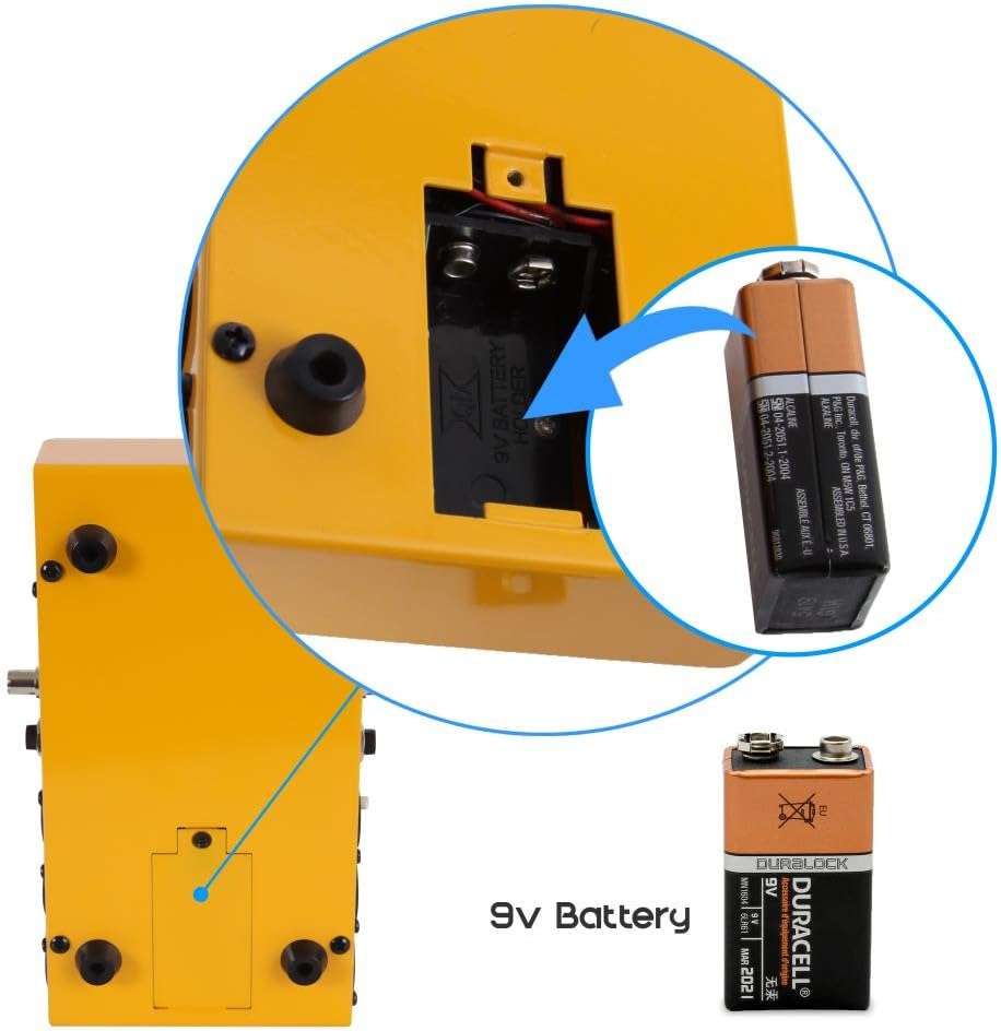
Figure 2: Illustration of the battery compartment and 9V battery installation.
Initial Battery Check
Before testing cables, it is recommended to check the battery level. Turn the rotary switch to the "Battery Check" position, typically located at the far right of the dial. The LED indicators will illuminate to show the battery status. If the LEDs are dim or do not light up, replace the 9V battery.
Operating Instructions
The Pyle PCT40 is designed for straightforward cable testing. Follow these general steps for most cable types:
General Cable Testing Procedure
- Ensure the unit has a fresh 9V battery installed and has passed the battery check.
- Connect one end of the cable to be tested into the appropriate input port on the left side of the PCT40.
- Connect the other end of the cable into the corresponding output port on the right side of the PCT40. For example, if testing an XLR male to XLR female cable, connect the male end to the XLR female port on the left and the female end to the XLR male port on the right.
- Turn the rotary switch to cycle through the pins. The illuminated LEDs will indicate the continuity of each pin connection.
- Observe the LED panel:
- Matching LEDs: If a pin on the left connector is connected to a pin on the right connector, the corresponding LEDs for both pins will illuminate simultaneously. For example, if pin 1 on the left XLR is connected to pin 1 on the right XLR, both '1' LEDs will light up.
- Single LED: If only one LED illuminates, it indicates an open circuit (broken wire) for that pin, or a short circuit if multiple LEDs light up unexpectedly.
- No LEDs: If no LEDs illuminate for a specific pin, it indicates an open circuit.
- Ground LED: A dedicated LED indicates ground connection status.
- Repeat for all pins by rotating the switch to thoroughly test the cable.

Figure 3: The Pyle PCT40 in operation, demonstrating cable connections and LED feedback.

Figure 4: Close-up view of the rotary switch and LED panel during cable testing.
Supported Cable Types
The PCT40 supports testing for the following cable connections:
- USB (Type A/B)
- ¼” TRS Jacks (6.3mm)
- 3-Pin XLR Male
- 3-Pin XLR Female
- 5-Pin XLR
- RCA Phono
- 4-Pin SpeakOn
- 4-Pin S-Type Jack
- Banana Plugs
- 3-Pin DIN
- 5-Pin DIN
- 8-Pin DIN
- RJ45

Figure 5: Diagram illustrating the various cable types supported by the PCT40.
Using the Banana Jacks for Continuity Testing
The PCT40 includes red and black banana jacks for custom continuity testing. This feature is useful for checking individual wires, components, or non-standard connections.
- Connect test leads (not included) with banana plugs into the red and black jacks.
- Touch the probes of the test leads to the points you wish to test for continuity.
- If continuity exists, the corresponding LED will illuminate, and an audible beep may sound (depending on the specific model's functionality).
Maintenance
Proper maintenance ensures the longevity and reliable operation of your Pyle PCT40 cable tester.
- Cleaning: Wipe the unit with a soft, dry cloth. Avoid using abrasive cleaners or solvents, which can damage the casing or labels.
- Battery Replacement: Replace the 9V battery when the battery check indicates low power or when LEDs appear dim during testing. Always dispose of used batteries responsibly.
- Storage: Store the PCT40 in a cool, dry place away from direct sunlight and extreme temperatures. If storing for extended periods, remove the battery to prevent leakage.
- Handling: While the unit is built with a rugged metal casing, avoid dropping or subjecting it to severe impacts to prevent damage to internal components or connectors.
Troubleshooting
If you encounter issues with your Pyle PCT40, refer to the following troubleshooting guide:
- No Power / LEDs Not Lighting Up:
- Check if a 9V battery is correctly installed.
- Perform a battery check. If the battery is low, replace it with a fresh 9V battery.
- Ensure the rotary switch is not in the "OFF" position (if applicable) or is set to a testing mode.
- Incorrect Readings / Inconsistent LED Behavior:
- Verify that the cable ends are fully and securely inserted into the correct ports on the tester.
- Ensure the rotary switch is set to the appropriate position for the pins being tested.
- Test a known good cable of the same type to confirm the tester is functioning correctly.
- Inspect the cable for visible damage or bent pins on its connectors.
- Banana Jack Continuity Test Not Working:
- Ensure test leads are properly connected to the banana jacks.
- Verify the test leads themselves are not faulty by shorting them together (the LED should light up).
Specifications
| Brand | Pyle |
| Model Number | PCT40 |
| Power Source | 1 x 9V Battery (not included) |
| Dimensions (L x W x H) | 8.2 x 4.7 x 2.8 inches (20.8 x 11.9 x 7.1 cm) |
| Item Weight | 0.5 Pounds (approx. 227 grams) |
| Supported Connectors | USB, ¼” TRS, 3-pin XLR (M/F), 5-pin XLR, RCA, 4-pin SpeakOn, 4-pin S-Type, Banana Plugs, 3-pin DIN, 5-pin DIN, 8-pin DIN, RJ45 |
| Casing Material | Metal |
Warranty and Support
For warranty information and technical support, please refer to the documentation included with your purchase or visit the official Pyle website. Keep your purchase receipt as proof of purchase for any warranty claims.
Online Resources: For additional support, FAQs, and product updates, please visit the Pyle official website.