1. Introduction
The Intermatic T104P is a heavy-duty 24-hour mechanical time switch designed for automatic control of electrical loads. This device provides reliable scheduling for various applications, offering up to 12 ON/OFF operations daily. Its robust plastic enclosure is suitable for both indoor and outdoor installations, providing protection against environmental elements.
Key features include direct 24-hour control, a minimum ON/OFF time of one hour, and a manual override function for temporary control adjustments.
2. Safety Information
WARNING: Risk of Electric Shock. Disconnect power at the circuit breaker or fuse before installing or servicing this time switch. Failure to do so may result in serious injury or death.
- Installation and servicing should be performed by a qualified electrician in accordance with all local and national electrical codes.
- This device operates at 208-277 VAC. Ensure proper voltage supply and wiring compatibility before installation.
- Do not connect aluminum wires directly to the switch terminals. Use appropriate copper-to-aluminum connectors if necessary.
- Ensure the enclosure is properly closed and secured after installation to maintain its NEMA 3R rating for outdoor use.
3. Package Contents
Verify that all items are present in the package:
- Intermatic T104P 24-Hour Mechanical Time Switch
- One (1) ON Tripper
- One (1) OFF Tripper
- Instruction Guide
4. Setup and Installation
4.1 Mounting the Time Switch
The T104P features a NEMA 3R rated plastic enclosure, suitable for both indoor and outdoor mounting. Choose a location that is easily accessible for programming and maintenance, and protected from direct impact.
- Open the enclosure door.
- Use appropriate screws or mounting hardware (not included) to secure the enclosure to a flat, stable surface through the designated mounting holes.
- Ensure the enclosure is level to allow for proper operation of the mechanical timer.
4.2 Wiring Instructions
Refer to the internal wiring diagram and the following steps for proper electrical connection. Always ensure power is disconnected before proceeding.

Figure 1: Internal view of Intermatic T104P mechanical time switch showing the yellow dial, manual lever, and wiring terminals. This image displays the internal components of the Intermatic T104P time switch, including the 24-hour dial for setting time, the manual ON/OFF lever, and the clearly labeled LINE and LOAD wiring terminals. A caution label regarding power disconnection and wire types is visible.
- Disconnect Power: Turn off power at the main circuit breaker or fuse panel before beginning any wiring.
- Access Terminals: The insulator covering the wiring terminals must be lifted and swung out of the way to access the connections. DO NOT REMOVE THIS INSULATOR.
- Connect Line Wires: Connect the incoming power supply wires (LINE) to the terminals labeled 'LINE'. This time switch is DPST (Double Pole Single Throw), meaning it controls two separate hot lines.
- Connect Load Wires: Connect the wires leading to the electrical load (e.g., pump, lighting) to the terminals labeled 'LOAD'.
- Grounding: Ensure the time switch is properly grounded according to local electrical codes.
- Secure Wires: Ensure all wire connections are tight and secure.
- Replace Insulator: Swing the insulator back into its original position, covering the wiring terminals.
- Close Enclosure: Close and secure the enclosure door.
- Restore Power: Turn power back on at the main circuit breaker or fuse panel.
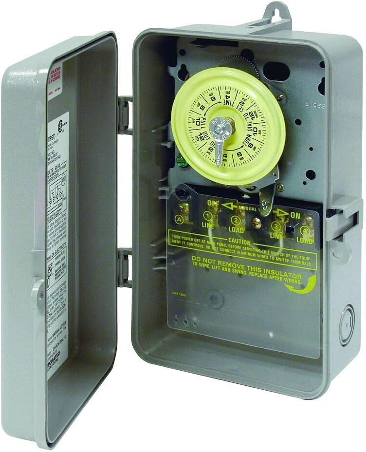
Figure 2: Side view of Intermatic T104P mechanical time switch with the gray plastic enclosure open, revealing the internal mechanism. This image shows the Intermatic T104P time switch with its gray plastic enclosure open, providing a view of the internal mechanical timer and the wiring compartment. The NEMA 3R rated enclosure is designed for both indoor and outdoor use.
5. Operating Instructions
5.1 Setting the Current Time
To set the current time, rotate the yellow dial clockwise until the current time of day aligns with the small arrow located at the top of the dial. Ensure to differentiate between AM and PM hours as indicated on the dial.
5.2 Setting ON/OFF Times
The T104P uses trippers to set the ON and OFF times. The unit comes with one ON tripper (green) and one OFF tripper (red).
- Install ON Tripper: Locate the green ON tripper. Push it onto the outer edge of the yellow dial at the desired time you want the connected load to turn ON.
- Install OFF Tripper: Locate the red OFF tripper. Push it onto the outer edge of the yellow dial at the desired time you want the connected load to turn OFF.
- Additional Cycles: The time switch supports up to 12 ON/OFF operations per day. Additional trippers can be purchased separately if more cycles are required. Each ON/OFF cycle requires one green ON tripper and one red OFF tripper.
- Minimum Interval: The minimum ON/OFF time interval is one hour. Ensure there is at least one hour between an ON and OFF tripper.
5.3 Manual Override
The time switch includes a manual override lever for temporary control of the connected load without affecting the programmed schedule.
- To manually turn the load ON or OFF, move the manual lever located below the dial to the desired position (ON or OFF).
- The next scheduled ON or OFF tripper will automatically restore the timer to its programmed schedule.
6. Maintenance
The Intermatic T104P is designed for minimal maintenance. However, periodic checks can ensure optimal performance and longevity.
- Cleaning: Periodically clean the exterior of the enclosure with a damp cloth. Do not use abrasive cleaners or solvents. Ensure the enclosure is dry before closing.
- Terminal Connections: Annually, with power disconnected, inspect wiring terminals for tightness and corrosion. Re-tighten if necessary.
- Dial and Trippers: Ensure the dial rotates freely and trippers are securely in place.
7. Troubleshooting
| Problem | Possible Cause | Solution |
|---|---|---|
| Load does not turn ON/OFF at programmed times. |
|
|
| Time switch dial is not rotating. |
|
|
| Enclosure door does not close properly. |
|
|
8. Specifications
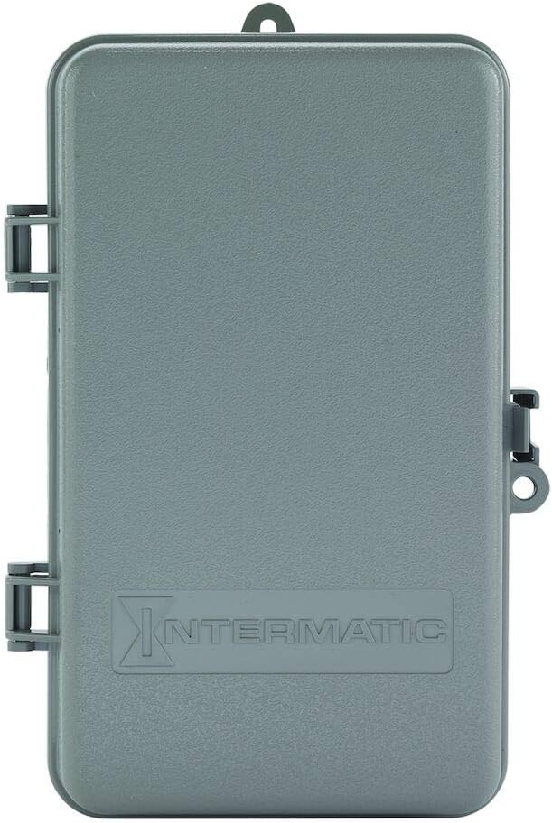
Figure 3: Front view of the Intermatic T104P mechanical time switch with its gray plastic enclosure closed, showing the Intermatic logo. This image presents the Intermatic T104P time switch with its durable gray plastic enclosure closed, suitable for protecting the internal components from environmental elements. The Intermatic brand logo is embossed on the front.
| Feature | Detail |
|---|---|
| Model | T104P |
| Type | 24-Hour Mechanical Time Switch |
| Voltage | 208-277 VAC |
| Frequency | 60 Hz |
| Number of Poles | 2 (DPST) |
| Amperage | 40 Amps |
| Horsepower (HP) Rating | 2 HP @ 120V, 5 HP @ 240V |
| Enclosure Type | Plastic, NEMA 3R (Indoor/Outdoor) |
| Minimum ON/OFF Time | 1 Hour |
| Maximum ON/OFF Cycles | 12 per day |
| Dimensions (H x W x D) | 9.43" x 5.5" x 3.81" |
| Item Weight | 2 Pounds |
| Material | Solid |
| Color | Gray |
9. Warranty and Support
For warranty information, please refer to the manufacturer's official documentation included with your product or visit the Intermatic brand store or their official website.
If you require technical assistance or have questions regarding the operation or installation of your Intermatic T104P time switch, please contact Intermatic customer support directly.


