
1. Introduction
This manual provides detailed instructions for the safe and effective use of the Mitutoyo 543-562A Digimatic Indicator. This precision instrument is designed for accurate linear distance and object size measurements in various industrial and laboratory settings. Please read this manual thoroughly before operating the device to ensure proper function and longevity.
2. Safety Information
Always observe the following safety precautions to prevent injury and damage to the instrument.
- Do not expose the indicator to direct sunlight, high temperatures, or extreme humidity.
- Avoid dropping or subjecting the instrument to strong impacts.
- Keep the indicator away from strong magnetic fields.
- Do not attempt to disassemble or modify the instrument. Refer all servicing to qualified personnel.
- Use only the specified power sources (AC adapter or 9V battery).
- Ensure the contact point is clean and free of debris before each measurement.
3. Product Overview
The Mitutoyo 543-562A Digimatic Indicator features a robust design for reliable performance.
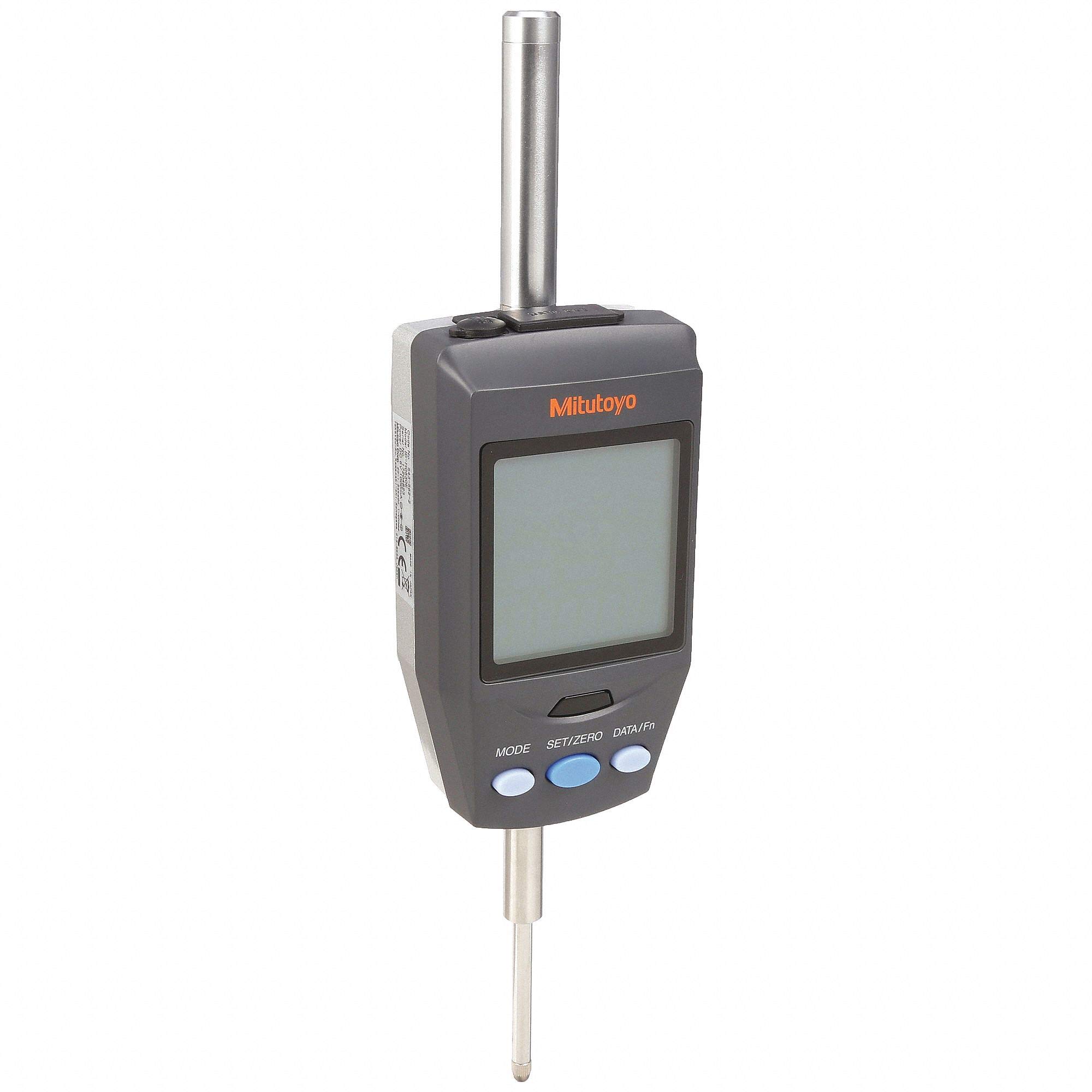
Figure 1: Mitutoyo 543-562A Digimatic Indicator. This image shows the front view of the digital indicator, highlighting its LCD display, control buttons, and the measuring spindle with a steel ball contact point. The main body is silver-colored, and the display is prominent.
3.1 Components
- LCD Display: Digital readout for measurements, unit indication, and function status.
- Control Buttons: For power, zero setting, unit conversion, and function selection.
- Measuring Spindle: The movable rod with a contact point for taking measurements.
- Contact Point: Steel ball tip for contacting the workpiece.
- Stem: 8mm diameter stem for mounting the indicator.
- Battery Compartment: Houses the 9V battery (if used).
- Data Output Port: RS-232C port for data transfer and SPC analysis.
- AC Adapter Port: For external power supply.
4. Setup
4.1 Power Supply
The indicator can be powered by either a 9V battery or an AC adapter.
- Battery Installation:
- Open the battery compartment cover on the back of the indicator.
- Insert a new 9V battery, ensuring correct polarity.
- Close the battery compartment cover securely.
- AC Adapter Connection:
- Connect the AC adapter to the AC adapter port on the indicator.
- Plug the AC adapter into a suitable power outlet.
4.2 Mounting the Indicator
Mount the indicator securely using its 8mm diameter stem.
- Insert the stem into a suitable indicator stand or fixture.
- Tighten the clamping mechanism on the stand to hold the indicator firmly in place.
- Ensure the indicator is positioned perpendicular to the surface being measured for optimal accuracy.
5. Operating Instructions
5.1 Power On/Off
- Press the ON/OFF button to turn the indicator on.
- Press and hold the ON/OFF button for a few seconds to turn the indicator off.
5.2 Zero Setting
The indicator can be set to zero at any spindle position.
- Position the contact point against the reference surface or workpiece.
- Press the ZERO button. The display will show "0.00000" (or equivalent in metric).
5.3 Unit Conversion
Toggle between inch and metric units.
- Press the IN/MM button to switch between inch and millimeter display.
5.4 Resolution Selection
The indicator offers five user-selectable resolutions.
- Press the RESOLUTION button (or equivalent) to cycle through available resolutions: 0.00002", 0.00005", 0.0001", 0.0005 mm, and 0.001 mm.
6. Measurement Modes and Functions
6.1 Max/Min Hold Function
This function captures and displays the maximum and minimum measured values during a sweep.
- Press the MAX/MIN button to activate the function.
- Move the contact point across the surface to be measured. The display will continuously update with the highest and lowest values detected.
- Press MAX/MIN again to exit the mode.
6.2 Total Indicator Reading (TIR)
TIR displays the absolute difference between the maximum and minimum readings.
- After performing a MAX/MIN sweep, press the TIR button (or equivalent).
- The display will show the calculated TIR value.
6.3 Tolerance Limit Setting
Set upper and lower tolerance limits. The display changes color (green to red) if measurements exceed these limits.
- Refer to the detailed instructions in the full product manual for specific button sequences to set upper and lower tolerance limits.
- Once set, the display will indicate out-of-tolerance conditions visually.
6.4 Data Output (RS-232C / SPC)
The indicator supports data output for statistical process control (SPC) and external analysis.
- Connect the indicator to a compatible data processor or computer using an RS-232C cable.
- Use appropriate software to capture and analyze the measurement data.
7. Maintenance
7.1 Cleaning
- Wipe the indicator body with a soft, dry cloth.
- For stubborn dirt, use a cloth lightly dampened with mild detergent, then wipe dry immediately.
- Do not use organic solvents (e.g., thinner, benzene) as they may damage the finish.
- Keep the measuring spindle and contact point clean and free of dust and oil.
7.2 Storage
- Store the indicator in its original case or a protective container when not in use.
- Avoid storing in areas with high humidity, extreme temperatures, or direct sunlight.
- Remove the battery if the indicator will not be used for an extended period to prevent leakage.
7.3 Battery Replacement
When the low voltage alarm appears on the display, replace the 9V battery as described in Section 4.1.
8. Troubleshooting
| Problem | Possible Cause | Solution |
|---|---|---|
| Display does not turn on. | Dead battery or no power from AC adapter. | Replace battery or check AC adapter connection. |
| Inaccurate readings. | Dirty contact point, improper mounting, or environmental factors. | Clean contact point, ensure secure and perpendicular mounting, avoid vibrations. |
| "Low Voltage" alarm. | Battery is low. | Replace the 9V battery. |
| "Overflow" error. | Measurement exceeds the indicator's range. | Ensure the measurement is within the 0-1.2 inch / 0-30.4 mm range. |
If problems persist, contact Mitutoyo customer support.
9. Specifications
| Feature | Detail |
|---|---|
| Model Number | 543-562A |
| Measurement Range | 0 - 1.2 inches / 0 - 30.4 mm |
| Resolution | Selectable: 0.00002", 0.00005", 0.0001", 0.0005 mm, 0.001 mm |
| Accuracy | ±0.00005" / ±0.0015 mm |
| Display | LCD with color change for tolerance limits |
| Ingress Protection (IP) Rating | IP30 (Dust and water protection) |
| Stem Diameter | 8 mm |
| Contact Point | Steel ball |
| Power Source | AC Adapter or 9V Battery |
| Data Output | RS-232C, SPC |
| Special Functions | Max/Min Hold, TIR, Tolerance Limit Setting, Backup Memory |
| Material | Stainless Steel |
| Item Weight | 295 g |
| Product Dimensions | 16.26 x 10.92 x 38.61 cm |
| Country of Origin | Japan |
10. Warranty and Support
Mitutoyo products are manufactured to high-quality standards. For specific warranty information, please refer to the warranty card included with your product or visit the official Mitutoyo website.
For technical support, service, or replacement parts, please contact your local authorized Mitutoyo distributor or Mitutoyo America Corporation directly.
- Mitutoyo America Corporation: Headquartered in Aurora, IL.
- Online Resources: www.mitutoyo.com


