1. Introduction
This manual provides detailed instructions for the installation, operation, and maintenance of the Potter PCVS-2 Indicator Valve Supervisory Switch. The PCVS-2 is designed to monitor the open position of a gate valve, providing a signal to a fire alarm control panel when the valve is not in its fully open position. Proper installation and regular maintenance are crucial for the reliable operation of fire protection systems.
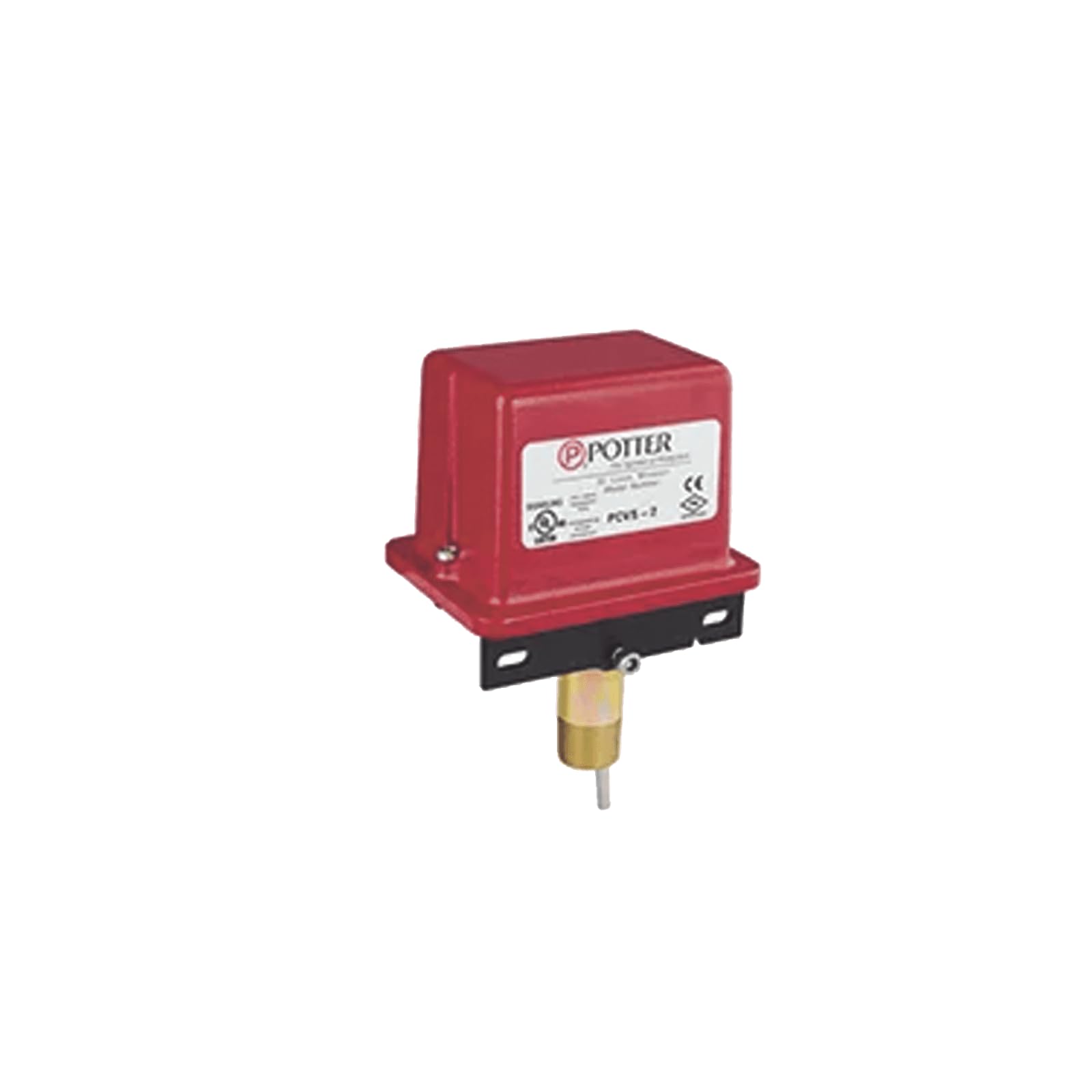
Figure 1: Potter PCVS-2 Indicator Valve Switch. This image shows the red housing of the switch with the Potter logo and model number PCVS-2 clearly visible on a white label. The metallic shaft for valve attachment extends from the bottom.
2. Safety Information
Read all instructions carefully before installation and operation. Failure to follow these instructions may result in property damage, serious injury, or death. This device must be installed by qualified personnel in accordance with all national and local codes and ordinances.
- Always disconnect power before servicing the device.
- Ensure all wiring connections are secure and comply with electrical codes.
- Do not modify the device in any way.
- Test the device regularly as required by applicable standards.
- Keep the device free from moisture and extreme temperatures.
3. Package Contents
Verify that all items are present and undamaged upon opening the package:
- Potter PCVS-2 Indicator Valve Supervisory Switch (1 unit)
- Installation Hardware (screws, mounting bracket if applicable)
- Instruction Manual (this document)
4. Specifications
| Feature | Specification |
|---|---|
| Brand | Potter |
| Model Number | PCVS-2 |
| Operation Mode | Automatic |
| Contact Type | Normally Open |
| Circuit Type | 1-way |
| Actuator Type | Electronic |
| Contact Material | Stainless Steel |
| International Protection Rating | IP00 |
| Number of Positions | 2 |
| Connectivity Protocol | Wi-Fi (Note: This specification might be a misclassification for a traditional valve switch. Refer to product documentation for exact connectivity.) |
| Color | Red |
| Material | Plastic |
| Switch Type | Toggle |
| Mounting Type | Panel Mount |
| Item Weight | 1 pounds |
| Package Dimensions | 9.57 x 3.78 x 3.19 inches |
| UPC | 785192000563 |
Note: Specifications are subject to change without notice. Always refer to the product's official data sheet for the most current information. The "Wi-Fi" and "App" control specifications appear to be generic classifications and may not apply to this specific mechanical supervisory switch.
5. Installation and Setup
5.1 Pre-Installation Checks
- Ensure the valve to be monitored is compatible with the PCVS-2 switch.
- Verify that the installation location provides adequate space for mounting and wiring.
- Confirm that all necessary tools and materials are available.
- Review local fire codes and electrical regulations.
5.2 Mounting the Switch
- Position the PCVS-2 switch on the valve's indicator post or operating mechanism according to the valve manufacturer's instructions.
- Secure the switch using the provided mounting hardware. Ensure the switch is firmly attached and does not interfere with valve operation.
- Adjust the switch mechanism to properly engage with the valve's indicator, ensuring it detects the fully open position accurately.
5.3 Wiring Connections
The PCVS-2 features screw terminals for electrical connections. Refer to the wiring diagram provided with the device or on the device label for specific connections to the fire alarm control panel (FACP).
- Connect the supervisory circuit wiring from the FACP to the designated screw terminals on the PCVS-2.
- Ensure polarity is correct if specified by the FACP or local codes.
- Tighten all screw terminals securely to prevent loose connections.
- After wiring, close the switch cover and secure it.
6. Operating Instructions
The Potter PCVS-2 is an automatic supervisory switch designed to monitor the position of a valve. It does not require manual operation for its primary function.
- When the monitored valve is in its fully open position, the PCVS-2 switch contacts are in their normal state (typically closed for supervisory circuits).
- If the valve is moved from its fully open position (e.g., partially closed or fully closed), the PCVS-2 switch will activate, changing the state of its contacts.
- This change in contact state signals the connected fire alarm control panel, initiating a supervisory alarm condition.
6.1 Testing the Switch
Regular testing is essential to ensure proper functionality. Consult local codes and standards (e.g., NFPA 25) for required testing frequencies.
- Notify relevant personnel that a test of the fire alarm system will be conducted.
- Partially close the valve being monitored by the PCVS-2 switch.
- Verify that a supervisory alarm signal is received at the fire alarm control panel within the specified time (typically within two revolutions of the valve handwheel or one-fifth of the way from the normal open position).
- Return the valve to its fully open position.
- Verify that the supervisory alarm clears at the FACP.
- Reset the FACP if necessary.
7. Maintenance
The Potter PCVS-2 switch requires minimal maintenance. However, periodic inspection and testing are critical for ensuring its continued reliability.
- Annual Inspection: Visually inspect the switch for any signs of physical damage, corrosion, or loose connections. Ensure the mounting is secure.
- Functional Testing: Perform functional tests as described in Section 6.1 at least annually, or more frequently as required by local codes and standards.
- Cleaning: Keep the exterior of the switch clean and free of dust or debris. Use a soft, dry cloth for cleaning. Do not use abrasive cleaners or solvents.
8. Troubleshooting
This section addresses common issues that may arise with the PCVS-2 switch. For problems not listed here, contact qualified service personnel.
| Problem | Possible Cause | Solution |
|---|---|---|
| No supervisory alarm when valve is closed. |
|
|
| Constant supervisory alarm. |
|
|
| Intermittent alarms. |
|
|
9. Warranty and Support
Potter Electric Signal Company products are manufactured under strict quality control standards. For specific warranty information, please refer to the official warranty statement provided with your product or visit the manufacturer's website.
For technical support, service, or replacement parts, please contact your authorized Potter distributor or the Potter Electric Signal Company directly. Ensure you have your product model number (PCVS-2) and serial number (if applicable) ready when contacting support.
Potter Electric Signal Company Contact Information:
www.pottersignal.com


