Introduction
This manual provides essential information for the proper installation, operation, and maintenance of your Powermaster 48237 High-Amp Alternator. Please read these instructions carefully before proceeding with installation or use to ensure optimal performance and safety.
Safety Information
- Always disconnect the vehicle's battery before working on the electrical system to prevent electrical shock or damage.
- Wear appropriate personal protective equipment, including safety glasses and gloves.
- Ensure the vehicle is securely supported if working underneath it.
- Consult a qualified automotive technician if you are unsure about any installation steps.
- This product contains chemicals known to the State of California to cause cancer and birth defects or other reproductive harm (Proposition 65 warning).
Setup and Installation
The Powermaster 48237 High-Amp Alternator is designed for vehicle-specific applications. While it is a direct replacement for many GM AD244 applications, some modifications may be necessary for optimal fit and performance, as detailed below.
Pre-Installation Checks
- Verify Compatibility: Confirm this alternator is suitable for your specific vehicle model and year.
- Inspect Pulley: Compare the pulley on the new alternator with your existing one. If the pulley size differs, you may need a different length belt.
- Check Electrical Connector: If your vehicle's alternator plug is square instead of oval, an adapter plug may be required.
Installation Steps
- Disconnect Battery: Disconnect the negative battery terminal first, then the positive terminal.
- Remove Old Alternator: Loosen and remove the serpentine belt. Disconnect all electrical connections from the old alternator. Remove mounting bolts and carefully extract the old alternator.
- Prepare New Alternator:
- Power Wire Upgrade: It is highly recommended to upgrade the main power wire from the alternator to the battery to a 4 AWG (American Wire Gauge) cable. The power post on this alternator is 3/8 inch in diameter, so ensure your terminal connector matches this size or enlarge it if necessary.
- Ground Wire: If your vehicle uses a separate ground wire for the alternator, ensure it is properly connected. If not, the alternator grounds through its mounting to the engine block.
- Mount New Alternator: Carefully position the Powermaster 48237 into the mounting cradle. Due to its robust construction, it may be slightly larger than a stock unit.
- The mounting bolt-hole distance (center-to-center) should be identical to stock. However, the bolt hole "width" may be slightly longer. Gentle persuasion (e.g., using a rubber mallet and wooden wedge) may be needed to align the mounting holes.
- Once aligned, insert and tighten the mounting bolts securely.
- Reconnect Electrical: Connect the main power wire to the 3/8 inch power post. Reconnect the vehicle's electrical plug.
- Install Serpentine Belt: Route the serpentine belt correctly and tension it according to your vehicle's specifications.
- Reconnect Battery: Reconnect the positive battery terminal first, then the negative terminal.
- Test System: Start the vehicle and check for proper charging voltage (typically 13.8V to 14.8V). Monitor the dashboard warning lights.
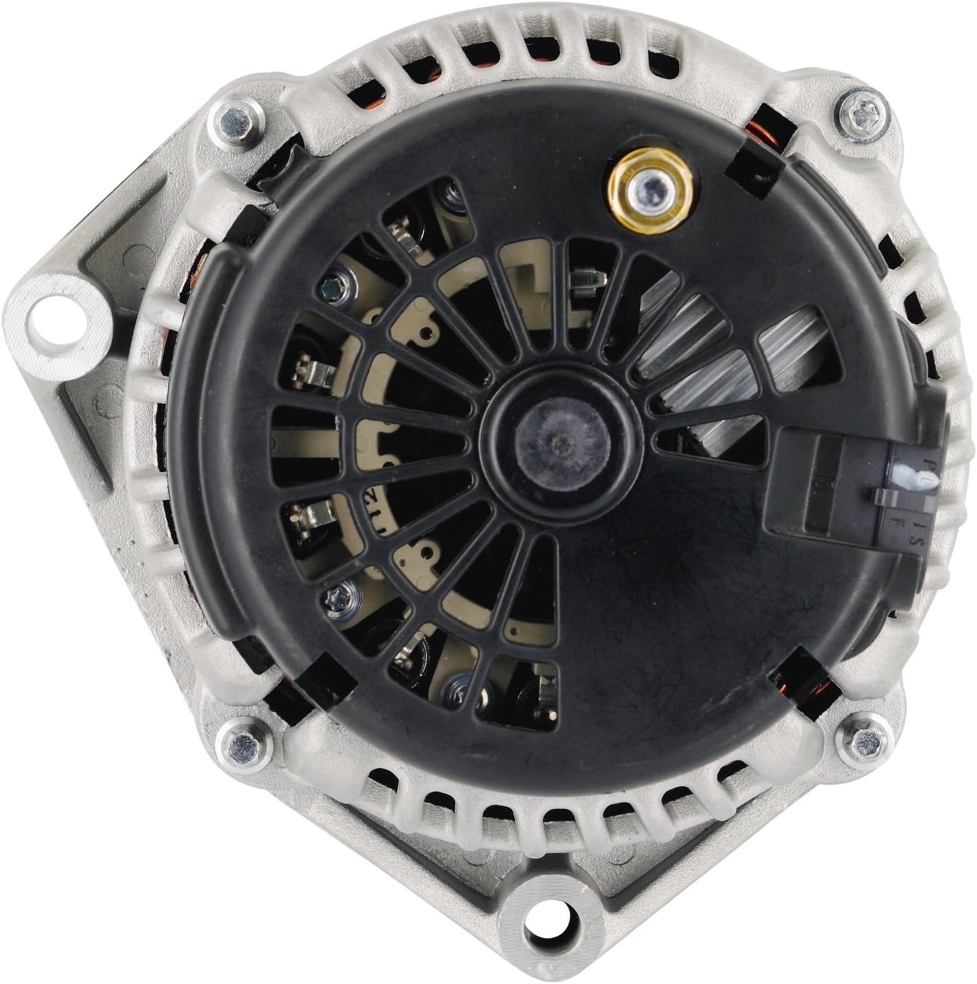
Image 1: Front view of the Powermaster 48237 High-Amp Alternator, showing the pulley and mounting points.

Image 2: Rear view of the Powermaster 48237 High-Amp Alternator, highlighting the electrical connections and cooling fan.
Operating Instructions
The Powermaster 48237 High-Amp Alternator is designed to provide superior electrical output for vehicles with increased power demands. Once correctly installed, it operates automatically as part of your vehicle's charging system.
- This alternator is rated for approximately 140-160 amps at idle and 195-222 amps at cruising speeds, depending on the specific unit and vehicle setup.
- Ensure your battery is in good condition to fully utilize the high output of this alternator. An AGM battery is often recommended for high-amp applications.
- Monitor your vehicle's voltage gauge to ensure stable charging.
Maintenance
Regular maintenance helps ensure the longevity and performance of your alternator.
- Belt Inspection: Periodically check the serpentine belt for cracks, fraying, or excessive wear. Ensure it is properly tensioned.
- Electrical Connections: Inspect all electrical connections to the alternator for corrosion or looseness. Clean and tighten as necessary.
- Battery Health: A healthy battery is crucial for the charging system. Have your battery tested regularly.
- Cleanliness: Keep the alternator free from excessive dirt, oil, and debris, which can impede cooling.
Troubleshooting
If you experience issues with your charging system, consider the following common troubleshooting steps:
| Symptom | Possible Cause | Solution |
|---|---|---|
| Battery Light On / Low Voltage |
|
|
| Bearing Noise from Alternator |
|
|
| Voltage Drop at High RPMs |
|
|
For persistent issues or problems not listed here, please contact Powermaster customer support or a certified automotive technician.
Specifications
- Model Number: 48237
- Brand: POWERMASTER
- Type: High-Amp Alternator (GM AD244 style)
- Output: Up to 220 Amps (typically 140-160A at idle, 195-222A at cruise)
- Part Number: 48237
- Item Weight: Approximately 15 Pounds (6.8 kg)
- Item Dimensions (LxWxH): Approximately 9 x 7.5 x 7.5 inches (22.86 x 19.05 x 19.05 cm)
- Material: Mixed (Metal, Plastic)
- Included Components: Powermaster - Alt GM AD244 Natural 220A 6 grv Pull
- Fit Type: Vehicle Specific
Warranty Information
This Powermaster alternator is covered by a Manufacturer Warranty. For specific details regarding warranty duration, coverage, and claims process, please refer to the warranty documentation included with your purchase or visit the official Powermaster website. Keep your proof of purchase for warranty purposes.
Customer Support
If you have any questions, require technical assistance, or need to report an issue with your Powermaster 48237 High-Amp Alternator, please contact Powermaster customer support directly. Contact information can typically be found on the product packaging or the manufacturer's official website.


