1. Introduction
Thank you for choosing the Tunze USA 7607/2 Water Level Alarm. This device is designed to monitor water levels and provide alerts for both run-dry and overflow conditions, ensuring the safety and proper functioning of your aquatic system. It features three independent sensors and a control unit with optical indicators and an audible alarm.
Please read this instruction manual carefully before installation and operation to ensure correct usage and to prevent damage to the unit or your system.
2. Safety Instructions
- Always disconnect the power supply before performing any maintenance or installation.
- Ensure the device is installed in a dry location, away from direct water splashes, unless specified for submersible use.
- Do not operate the device if the power cord or plug is damaged.
- This device is designed for indoor use only.
- Keep out of reach of children.
- The switched socket outlet has a maximum switching capacity of 230V / 1,800W (at 115V / 900W). Do not exceed this limit.
3. Package Contents
Verify that all components are present in the package:
- 1x Tunze USA 7607/2 Control Unit
- 3x Water Level Sensors (1x run-dry, 2x overflow)
- 3x Sensor Holding Devices
- 1x Power Cable with Switched Socket Outlet
- 1x Instruction Manual (this document)
4. Product Overview
The Tunze USA 7607/2 Water Level Alarm consists of a central control unit and three independent float sensors. The control unit provides visual feedback via optical indicators for each sensor and an audible alarm for critical events. The sensors are designed for flexible mounting within your system.
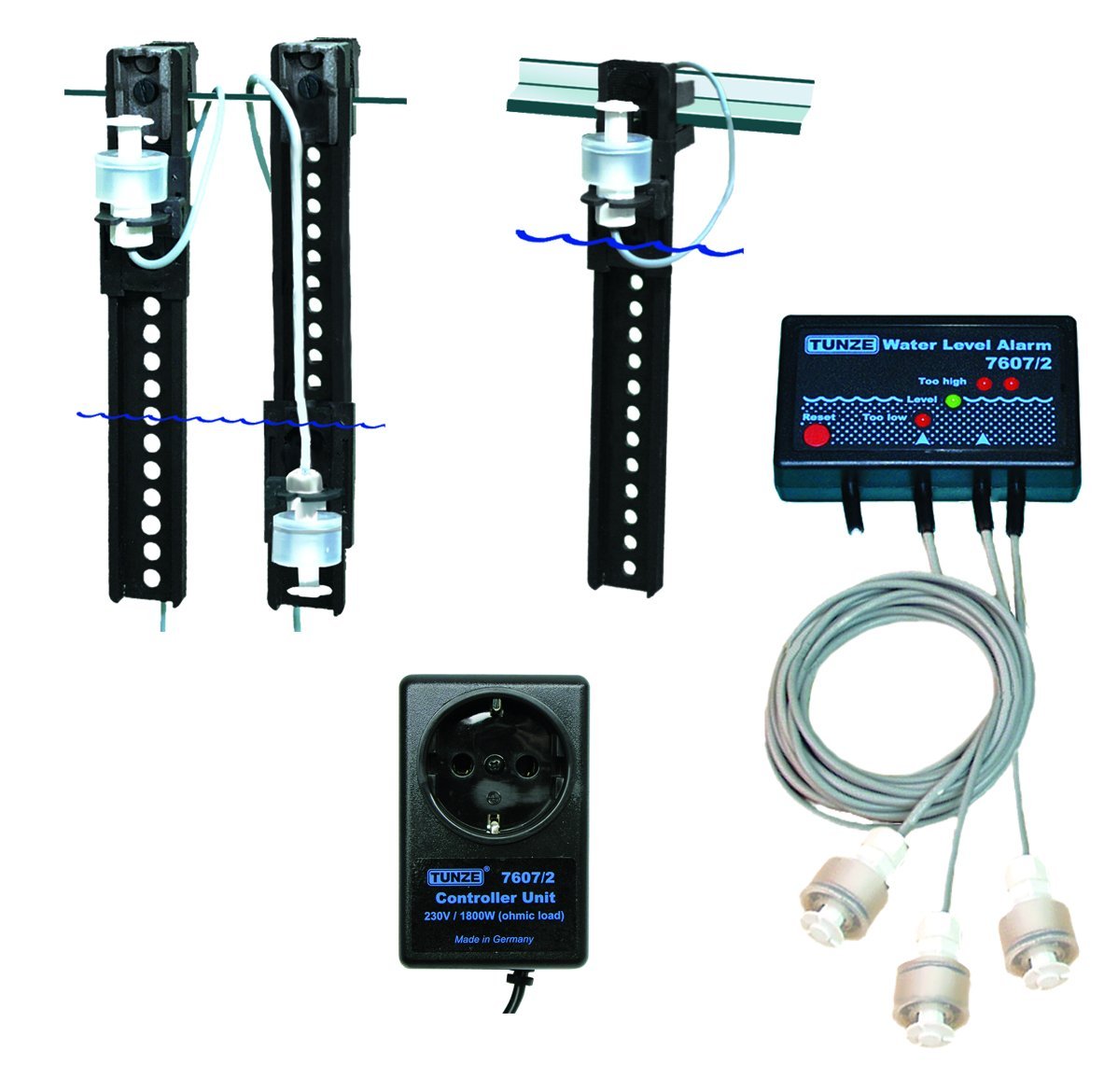
Figure 1: Tunze USA 7607/2 Water Level Alarm components. This image displays the main control unit, three water level sensors, and their respective holding devices.
4.1 Control Unit
- Optical Indicators: Individual lights for each of the three sensors, indicating their status.
- Audible Alarm: Emits a sound when a critical water level is detected.
- Switched Socket Outlet: Connects to a pump or other device, allowing it to be switched on/off based on sensor input.
4.2 Sensors
- Run-Dry Sensor: Typically placed at a low water level to prevent pumps from running dry.
- Overflow Sensors (x2): Placed at higher water levels to detect potential overflows.
- Holding Devices: Can be attached with silicone or clamped to horizontal or vertical panes. Multiple holding devices can be combined for custom configurations.
5. Setup and Installation
- Mount the Control Unit: Choose a dry, easily accessible location for the control unit. Ensure it is securely mounted and protected from splashes.
- Position the Sensors:
- Determine the desired water levels for run-dry and overflow detection.
- Attach the sensor holding devices to your tank or sump using silicone or by clamping them to the panes.
- Insert the sensors into their respective holding devices. Ensure the float mechanism moves freely.
- Connect the sensor cables to the corresponding ports on the control unit.
- Connect the Pump (Optional): If you wish to control a pump, plug the pump's power cord into the switched socket outlet on the control unit.
- Power On: Plug the control unit's power cord into a suitable electrical outlet. The optical indicators should illuminate briefly during startup.
Note: For optimal performance, ensure sensor cables are routed neatly and securely to prevent accidental dislodgement.
6. Operating Instructions
Once installed and powered on, the Tunze USA 7607/2 Water Level Alarm continuously monitors the water levels via its three sensors.
6.1 Sensor Indicators
- Each sensor has a corresponding optical indicator on the control unit.
- When a sensor detects a critical water level (e.g., water too low for run-dry, water too high for overflow), its indicator light will change state (e.g., from green to red, or off to on, depending on the specific model's design).
6.2 Audible Alarm
- Upon detection of a critical water level by any of the configured sensors, the control unit will emit an audible alarm.
- The alarm serves as an immediate notification of a potential issue.
- Consult the troubleshooting section for steps to address the alarm condition.
6.3 Switched Socket Outlet Functionality
- The switched socket outlet can be configured to turn a connected pump ON or OFF based on specific sensor triggers.
- For example, it can turn off a return pump if the run-dry sensor is triggered, or turn on an emergency drain pump if an overflow sensor is triggered. Refer to the specific wiring diagram or advanced settings in the full manual for detailed configuration options.
7. Maintenance
- Regular Cleaning: Periodically clean the sensors to prevent algae, calcium, or other debris buildup that could impede the float mechanism. Use a soft brush and warm water. Do not use harsh chemicals.
- Sensor Check: Manually test each sensor periodically by gently moving the float to ensure it triggers correctly. Observe the optical indicators on the control unit.
- Cable Inspection: Inspect all cables for signs of wear, damage, or corrosion. Replace damaged cables immediately.
- Control Unit: Keep the control unit clean and dry. Wipe with a soft, damp cloth if necessary.
8. Troubleshooting
| Problem | Possible Cause | Solution |
|---|---|---|
| Alarm sounds continuously or falsely. |
|
|
| No power to the control unit. |
|
|
| Connected pump does not turn on/off. |
|
|
If the problem persists after attempting these solutions, please contact Tunze USA customer support.
9. Specifications
- Model: 7607/2
- Manufacturer: Tunze USA LLC
- Product Dimensions: 6.35 x 5.08 x 2.54 cm (2.5 x 2 x 1 inches)
- Item Weight: 1.59 kg (3.5 Pounds)
- Voltage: 230 Volts (Control unit input)
- Switched Socket Capacity: Up to 230V / 1,800W (at 115V / 900W)
- Sensors: 3 (1x run-dry, 2x overflow)
10. Warranty and Support
For warranty information and technical support, please refer to the official Tunze USA website or contact their customer service directly. Keep your purchase receipt as proof of purchase.
Tunze USA Contact Information:
- Website: www.tunze.com/us/ (Please check for the most current contact details)
- Customer Service: Refer to the website for phone numbers or email support.


