
1. Introduction
Welcome to the user manual for your new AeroCool M40 MicroATX computer case. This manual provides essential information for the proper installation, operation, and maintenance of your chassis. Please read these instructions carefully before beginning assembly to ensure optimal performance and longevity of your system components.
The AeroCool M40 is a compact MicroATX case designed with a unique double-deck chassis for easy access and efficient component organization. It supports Micro ATX motherboards and standard ATX power supplies, offering flexibility for various system builds.
Safety Precautions
- Always disconnect the power supply from the wall outlet before installing or removing any components.
- Wear an anti-static wrist strap to prevent electrostatic discharge (ESD) damage to sensitive components.
- Handle components with care, avoiding contact with pins and circuit boards.
- Ensure proper ventilation around the case to prevent overheating.
2. Product Overview
The AeroCool M40 MicroATX case features a robust design with a focus on accessibility and cooling efficiency. Its innovative double-deck chassis simplifies component installation and cable management.
Key Features
- Unique Cube Design: Micro ATX case with a double-deck chassis for easy installation access.
- Front Panel Connectivity: Includes 4 x USB 2.0 ports and AC97 Mic and Audio ports for convenient peripheral connection.
- Enhanced Cooling: Supports up to 4 fans for effective system cooling.
- Integrated Monitoring: Features a fan and temperature monitor LCD display on the front panel.
- Durable Construction: Solidly constructed chassis interior with 0.6mm SECC steel.
Case Components
Below is an image illustrating the general layout of the AeroCool M40 case.
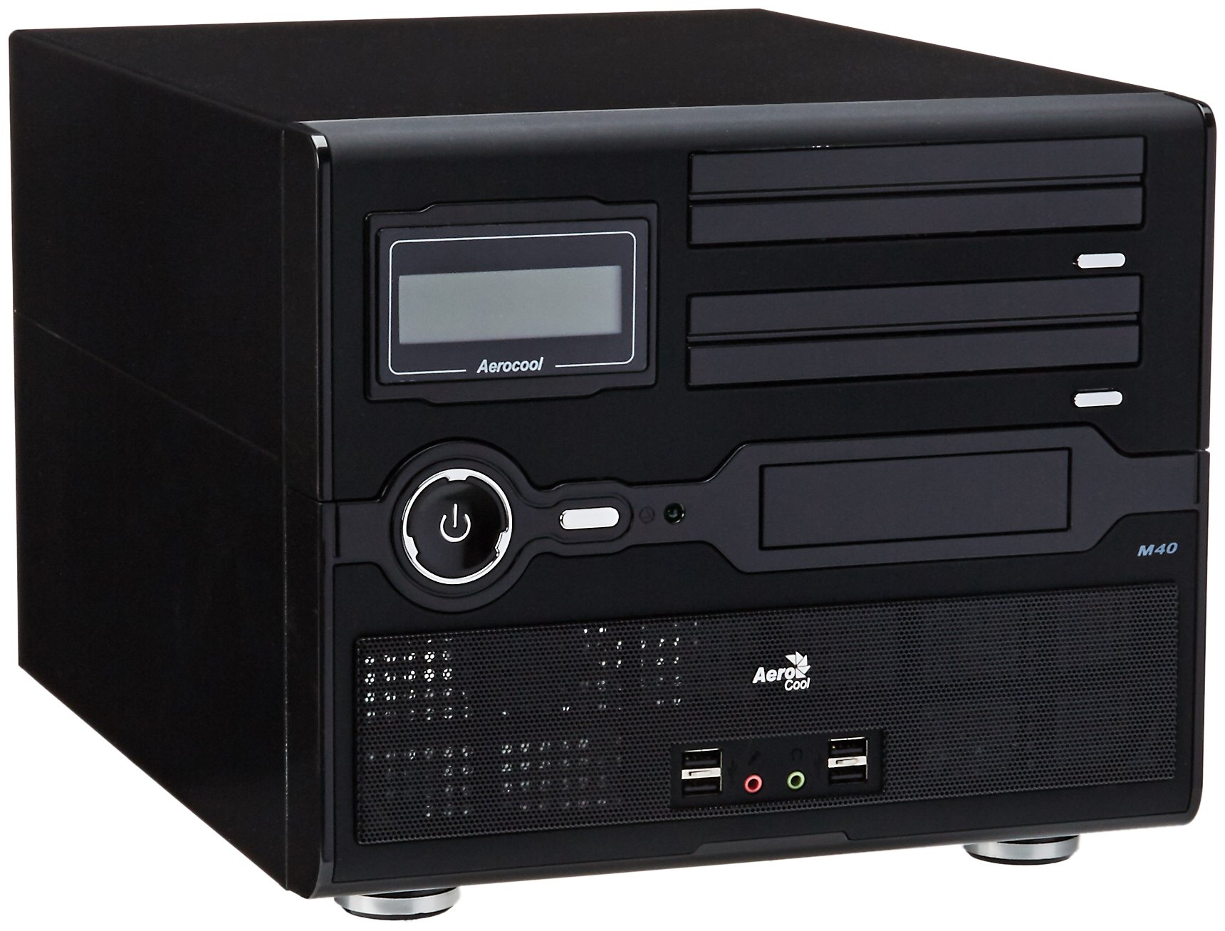
Figure 2.1: AeroCool M40 MicroATX Case (Front and Side View)
This image displays the front and side profile of the AeroCool M40 case, highlighting its compact cube design. The front panel includes the LCD display and I/O ports. The side panel is removable for internal access.
The rear panel of the AeroCool M40 case typically includes:
- Rear Fan Mount: Location for an exhaust fan to aid in cooling.
- Motherboard I/O Shield Cutout: Area for the motherboard's input/output ports.
- Expansion Slots: Multiple slots for graphics cards and other expansion cards.
- Power Supply Unit (PSU) Mount: Area for installing the power supply.
3. Setup Instructions
Follow these steps to assemble your computer system within the AeroCool M40 case.
3.1. Opening the Case
- Place the case on a flat, stable surface.
- Locate the thumbscrews or screws on the rear panel that secure the side panel. Remove these screws.
- Gently slide the side panel backward and then lift it off to expose the interior.
- The M40 features a double-deck chassis. The upper section is hinged and can be opened to provide ample space for motherboard installation. Carefully open the upper section and secure it with the integrated leg or support mechanism if available.
3.2. Motherboard Installation
- Install the I/O shield provided with your Micro ATX motherboard into the cutout on the rear of the case.
- Ensure that the standoffs for the Micro ATX motherboard are correctly aligned and installed on the motherboard tray.
- Carefully place your Micro ATX motherboard onto the standoffs, aligning the screw holes.
- Secure the motherboard with the appropriate screws. Do not overtighten.
3.3. Power Supply Unit (PSU) Installation
The AeroCool M40 supports standard ATX power supplies. It is recommended to use a PSU with a depth of 140mm or less for optimal compatibility, especially concerning drive cage placement.
- Position the PSU in its designated mounting area, typically at the rear of the upper section.
- Secure the PSU to the case using the screws provided with the PSU or case.
- Route the necessary power cables to the motherboard and other components, utilizing cable management features of the case where possible.
3.4. Drive Installation
The case supports 2.5-inch hard disk form factor drives.
- Locate the drive bays or mounting points for 2.5-inch drives. These are often found in the lower section or removable cages.
- Mount your SSDs or HDDs into the drive bays using the provided screws or tool-less mechanisms.
- Connect the SATA data and power cables to the installed drives.
3.5. Fan Installation
The AeroCool M40 supports up to 4 fans for enhanced cooling.
- Identify the fan mounting locations (e.g., front, rear, side, top).
- Install fans into the desired locations, ensuring proper airflow direction (intake or exhaust).
- Secure fans with screws.
- Connect fan power cables to the motherboard fan headers or a fan controller.
3.6. Connecting Front Panel I/O
Connect the front panel cables to the corresponding headers on your motherboard.
- USB 2.0: Connect the USB 2.0 header cable to the motherboard's USB 2.0 header.
- Audio (AC97): Connect the AC97 audio cable to the motherboard's front panel audio header.
- Power/Reset/LEDs: Connect the power switch, reset switch, power LED, and HDD activity LED cables to their respective motherboard headers. Refer to your motherboard manual for exact pinouts.
- Front Panel LCD: Connect the LCD display's power and data cables as per the instructions provided with the case or display unit.
3.7. Closing the Case
- Once all components are installed and cables are managed, carefully close the hinged upper section of the chassis.
- Reattach the side panel by sliding it into place and securing it with the thumbscrews or screws removed earlier.
4. Operating Instructions
After successful assembly, your AeroCool M40 case is ready for operation.
4.1. Powering On/Off
- Connect the power cable from your PSU to a wall outlet.
- Press the power button on the front panel of the case to turn on your computer.
- To turn off, use the operating system's shutdown function or press and hold the power button for several seconds for a forced shutdown (not recommended for regular use).
4.2. Front Panel LCD Display
The front panel features an LCD display that monitors fan activity and temperature. This display provides real-time information on your system's thermal status and fan operation.
- Observe the display for temperature readings and fan indicators.
- Ensure the temperature sensor is correctly placed within the case for accurate readings.
5. Maintenance
Regular maintenance helps ensure optimal performance and extends the lifespan of your computer components.
5.1. Cleaning the Case
- Exterior: Use a soft, damp cloth to wipe down the exterior surfaces. Avoid abrasive cleaners.
- Interior: Periodically open the case and use compressed air to remove dust buildup from fans, heatsinks, and other components. Ensure the system is powered off and unplugged before cleaning the interior.
- Dust Filters: If your case includes removable dust filters, clean them regularly by rinsing with water and allowing them to dry completely before reinstallation.
5.2. Fan Maintenance
Check fans periodically for excessive dust accumulation or unusual noises. Clean or replace fans as necessary to maintain adequate airflow.
6. Troubleshooting
This section addresses common issues you might encounter.
Common Issues and Solutions
- System does not power on:
- Ensure the PSU is properly connected to the wall outlet and the power switch on the PSU is in the 'ON' position.
- Verify that the front panel power switch cable is correctly connected to the motherboard header.
- Check all power connections to the motherboard and components.
- Fans are not spinning:
- Confirm that fan power cables are securely connected to the motherboard or fan controller.
- Check BIOS/UEFI settings for fan control.
- Front panel USB/Audio ports not working:
- Ensure the front panel USB and audio cables are correctly connected to the motherboard headers.
- Check motherboard drivers for USB and audio.
- Front panel LCD display not working:
- Verify that the display's power and data cables are properly connected.
For issues related to specific components (motherboard, CPU, GPU, etc.), refer to their respective user manuals.
7. Specifications
| Feature | Specification |
|---|---|
| Brand | AeroCool |
| Model | M40 |
| Motherboard Compatibility | Micro ATX |
| Material | Alloy Steel (0.6mm SECC) |
| Cooling Method | Air |
| Supported Fans | Up to 4 fans |
| Fan Size (Included) | 120mm (front, included) |
| Front I/O Ports | 4 x USB 2.0, AC97 Mic, AC97 Audio |
| Hard Disk Form Factor | 2.5 Inches |
| Item Weight | 5.9 kg |
| UPC | 841269020855 |
8. Warranty and Support
8.1. Warranty Information
The AeroCool M40 MicroATX case comes with a 1-year warranty covering parts and labor from the date of purchase. This warranty covers manufacturing defects and malfunctions under normal use. It does not cover damage caused by misuse, accidents, unauthorized modifications, or improper installation.
Please retain your proof of purchase for warranty claims.
8.2. Technical Support
For technical assistance or warranty inquiries, please contact AeroCool customer support through their official website or the retailer where the product was purchased. Have your product model number (M40) and proof of purchase ready when contacting support.