1. Introduction
This manual provides essential information for the safe operation, maintenance, and setup of your Powermatic Model 201 22-Inch Planer. Please read this manual thoroughly before operating the machine to ensure proper use and to prevent injury or damage. Keep this manual accessible for future reference.

Image 1.1: The Powermatic Model 201 22-Inch Planer, a heavy-duty woodworking machine designed for precise material thickness reduction.
2. Safety Information
WARNING: Operating this equipment can expose you to chemicals including wood dust, which is known to the State of California to cause cancer. For more information go to www.P65Warnings.ca.gov.
Always follow basic safety precautions to reduce the risk of fire, electric shock, and personal injury. This includes, but is not limited to:
- Read and understand all instructions before operating the planer.
- Wear appropriate personal protective equipment (PPE), including eye protection, hearing protection, and dust masks.
- Ensure the work area is clean, well-lit, and free from obstructions.
- Never operate the machine under the influence of drugs, alcohol, or medication.
- Disconnect power before performing any maintenance, adjustments, or when changing knives.
- Keep hands and fingers away from the cutterhead and feed rollers during operation.
- Securely fasten the machine to a stable surface to prevent movement during operation.
- Ensure proper dust collection is connected and functioning to minimize airborne dust.
3. Key Features and Components
The Powermatic Model 201 Planer is engineered with several features to enhance performance and durability:
- Straight Knife Cutterhead: Equipped with four high-speed steel knives for a clean, smooth cut.
- Two Feed Speeds: Offers 20 and 30 feet per minute (fpm) to accommodate both rough and fine finishing work.
- Adjustable Bed Rollers: Allows for smooth feeding of various workpiece types, whether rough or finished.
- All Cast Iron Construction: Provides heavy-duty stability and rigidity, with the table traveling on two large lead screws.
- Dust Chute with 5-inch Port: Facilitates efficient dust collection when connected to a suitable system.
- Roller Bearing-Mounted Feed Rollers: Ensures smooth operation and extended service life.
- Segmented Infeed Roller with Sectional Chip Breaker: Designed to allow planing of multiple boards simultaneously, even with slight height variations.

Image 3.1: Close-up view of the straight knife cutterhead, featuring four high-speed steel (HSS) knives for efficient material removal.

Image 3.2: Detail of the segmented infeed roller and sectional chip breaker, which allows for planing of multiple workpieces at once.

Image 3.3: The large 5-inch dust port, designed for effective connection to a dust collection system.
4. Setup and Installation
Proper setup is crucial for safe and effective operation. Follow these general steps:
- Unpacking: Carefully remove the planer from its packaging. Inspect for any shipping damage.
- Placement: Position the planer on a level, stable surface capable of supporting its weight (approximately 1350 lbs). Ensure adequate space around the machine for safe operation and material handling.
- Assembly: Attach any components that were removed for shipping, such as the dust chute or handwheels, following the detailed instructions in the full product manual.
- Electrical Connection: Connect the planer to a dedicated 230V, single-phase power supply as specified. Ensure the electrical circuit meets the machine's requirements and is properly grounded.
- Dust Collection: Connect a suitable dust collection system to the 5-inch dust port. Proper dust collection is essential for safety and machine longevity.
- Table Parallelism: Verify and adjust the table parallelism using the adjustable collars to ensure consistent planing depth across the workpiece.

Image 4.1: Adjustable collars located beneath the table, used to fine-tune table parallelism for accurate planing.
5. Operating Instructions
Before operating, ensure all safety checks are complete and the machine is properly set up.
- Material Preparation: Select appropriate lumber. Ensure it is free of knots, nails, or other foreign objects. The workpiece should be flat on one face before planing for thickness.
- Thickness Adjustment: Use the handwheel to raise or lower the planer table to the desired thickness. Each turn of the handwheel adjusts the table by 1/16 inch.
- Feed Speed Selection: Choose the appropriate feed speed (20 fpm for fine finish, 30 fpm for rough work) using the two-speed gearbox control.
- Power On: Start the planer motor. Allow it to reach full operating speed before feeding material.
- Feeding Material: Carefully feed the workpiece into the infeed rollers. The anti-kickback fingers will engage to prevent material from being ejected back towards the operator. Maintain a firm but gentle pressure to assist the feed rollers.
- Planing Process: Allow the machine to feed the material through. Do not force the workpiece. Take light cuts, especially on wide or hard stock, to achieve the best finish and prevent motor overload.
- Power Off: Once planing is complete, turn off the planer and wait for all moving parts to stop before leaving the machine or performing any adjustments.

Image 5.1: The two-speed gearbox control, allowing selection between 20 and 30 feet per minute feed rates.

Image 5.2: The smart feed system, including anti-kickback fingers, designed to ensure safe and consistent material feeding.
6. Maintenance
Regular maintenance ensures optimal performance and extends the life of your planer. Always disconnect power before performing any maintenance.
- Cleaning: After each use, clean the machine thoroughly, especially the table, rollers, and cutterhead area, to remove wood chips and resin buildup.
- Knife Inspection and Replacement: Regularly inspect the cutterhead knives for sharpness and damage. Dull or nicked knives should be replaced or sharpened promptly to ensure a smooth finish and prevent excessive motor strain. Refer to the full manual for detailed knife replacement procedures.
- Lubrication: Periodically lubricate moving parts as specified in the detailed manual. This includes lead screws and chain drives.
- Belt Tension: Check drive belt tension periodically and adjust if necessary.
- Dust Collection System: Ensure your dust collection system is clean and operating efficiently.
7. Troubleshooting
This section addresses common issues you might encounter. For more complex problems, consult the full service manual or contact Powermatic customer support.
| Problem | Possible Cause | Solution |
|---|---|---|
| Poor surface finish (e.g., snipe, chatter marks) | Dull knives, incorrect bed roller adjustment, excessive depth of cut | Replace/sharpen knives, adjust bed rollers, reduce depth of cut |
| Material not feeding | Feed rollers clogged with resin, insufficient pressure, motor overload | Clean rollers, adjust roller pressure, check motor for issues |
| Motor stalls or overheats | Excessive depth of cut, dull knives, insufficient power supply | Reduce cut depth, replace knives, verify power supply meets requirements |
| Excessive vibration | Unbalanced cutterhead, loose components, machine not securely mounted | Inspect cutterhead, tighten fasteners, ensure stable mounting |
8. Specifications
| Specification | Value |
|---|---|
| Brand | Powermatic |
| Model Number | 201 |
| Material | Alloy Steel, Cast Iron |
| Product Dimensions (L x W x H) | 49" x 42" x 59" |
| Item Weight | 1350 Pounds |
| Style | Straight Knife Cutterhead |
| Power Source | Corded Electric |
| Cutting Depth (Max) | 0.19 Inches |
| Included Components | Planer, Dust Chute, Hardware, Wrenches |
| Maximum Rotational Speed | 4800 RPM |
| Voltage | 230 Volts |
| Horsepower | 7.50 HP |
| UPC | 662755296970 |
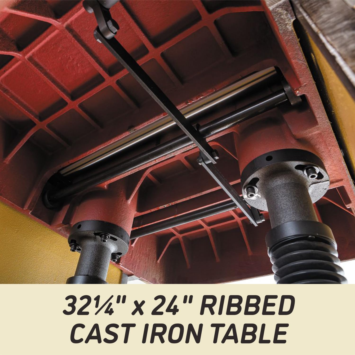
Image 8.1: The robust 32 1/4 inch by 24 inch ribbed cast iron table, providing a stable and durable work surface.
9. Warranty Information
The Powermatic Model 201 Planer comes with a 5-Year Limited Warranty. This warranty covers defects in materials and workmanship under normal use. For specific terms, conditions, and limitations, please refer to the official warranty document included with your product or visit the Powermatic website.

Image 9.1: Graphic indicating the 5-year warranty period for the product.
10. Customer Support
For technical assistance, parts, or service inquiries, please contact Powermatic customer support. Have your model number (201) and serial number ready when contacting support to expedite assistance.
Visit the official Powermatic website for additional resources, FAQs, and contact information: www.powermatic.com