1. Introduction
This manual provides essential information for the safe installation, operation, and maintenance of the Pilz PNOZ X2.1 24VAC/DC 2n/o Safety Relay, Model 774306. The PNOZ X2.1 is designed for monitoring safety functions such as E-STOP pushbuttons, safety gates, and light grids.
It is crucial to read and understand this manual completely before attempting any work with the device. Keep this manual accessible for future reference.
2. Safety Information
WARNING: Failure to follow these safety instructions can result in death, serious injury, or property damage.
- Only qualified personnel familiar with safety technology and electrical systems should install, operate, or maintain this device.
- Always disconnect power before performing any installation or maintenance work.
- Ensure all wiring complies with local and national electrical codes and standards.
- Do not bypass or disable safety functions.
- Regularly inspect the device and associated safety circuits for damage or malfunction.
- The PNOZ X2.1 is a safety component. Its proper function is critical for personnel safety.
3. Product Description
The Pilz PNOZ X2.1 is a safety relay designed for monitoring safety functions. It features 2 normally open (n/o) safety contacts and operates on a 24VAC/DC supply voltage. This device is part of the PNOZ X series, known for its robust and reliable safety solutions.
Key Features:
- Monitors E-STOP pushbuttons, safety gates, and light grids.
- 2 safety contacts (normally open).
- Supply voltage: 24VAC/DC.
- Automatic operation mode.
- DIN Rail Mount for easy installation.
- Screw type connectors.

Figure 1: Front view of the Pilz PNOZ X2.1 safety relay, showing the terminal connections and status indicators. The terminals are labeled A1, S33, S34, 13, 23, 24, S21, S22, 14, S11, S12, A2, and POWER, CH.1, CH.2 indicators.
4. Setup and Installation
The PNOZ X2.1 safety relay is designed for DIN rail mounting. Follow these steps for proper installation:
- Mounting: Securely attach the PNOZ X2.1 to a standard DIN rail in an appropriate control cabinet. Ensure adequate ventilation around the device.
- Power Supply Connection: Connect the 24VAC/DC power supply to terminals A1 and A2. Refer to the device labeling for correct polarity if using DC.
- Input Circuit Wiring:
- For E-STOP or Safety Gate monitoring: Connect the safety device (e.g., E-STOP pushbutton, safety gate switch) to terminals S33 and S34. Ensure the input circuit is correctly configured for the specific safety application.
- For Light Grid monitoring: Refer to the light grid manufacturer's instructions for connecting its output to S33 and S34.
- Output Circuit Wiring: Connect the load (e.g., contactor coil) to the safety output contacts. The safety outputs are 13-14 and 23-24. These are normally open (n/o) contacts that close when the safety function is active.
- Feedback Loop (if applicable): If a feedback loop is required for external contactors, connect it to terminals S21 and S22. This monitors the state of external contactors.
- Testing: After wiring, perform a thorough functional test of the entire safety circuit according to relevant standards and regulations before commissioning.
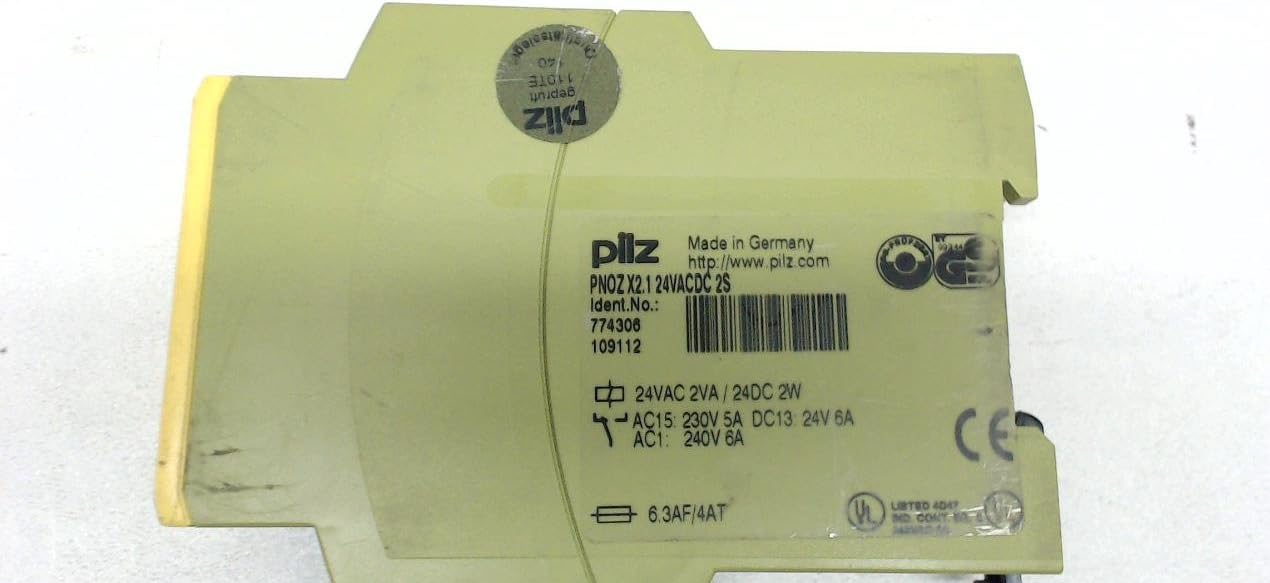
Figure 2: Rear view of the Pilz PNOZ X2.1 safety relay, showing the product label with model number (774306), electrical ratings (24VAC 2VA / 24VDC 2W, AC15 230V 5A, DC13 24V 6A, AC1 240V 6A), and certifications (CE, UL Listed).
5. Operating Instructions
The PNOZ X2.1 operates automatically once correctly installed and powered. Its primary function is to monitor safety inputs and control safety outputs.
- Power On: Apply 24VAC/DC power to terminals A1 and A2. The "POWER" LED indicator on the front of the device should illuminate.
- Input Monitoring: The device continuously monitors the state of the connected safety inputs (S33/S34).
- When the safety input circuit is closed (e.g., E-STOP released, safety gate closed), the "CH.1" and "CH.2" LEDs will illuminate, indicating that the input channels are active.
- When the safety input circuit is opened (e.g., E-STOP pressed, safety gate opened), the "CH.1" and "CH.2" LEDs will extinguish, and the safety outputs will open.
- Output Activation: If the safety input circuit is closed and all internal conditions are met, the safety output contacts (13-14, 23-24) will close, allowing power to flow to the connected load.
- Reset Function: The PNOZ X2.1 typically features an automatic reset. Once the safety input fault is cleared (e.g., E-STOP released), the device will automatically re-enable the safety outputs. Verify the specific reset behavior for your application.
6. Maintenance
The Pilz PNOZ X2.1 safety relay is designed for minimal maintenance. However, regular inspections are essential to ensure continued safe operation.
- Visual Inspection: Periodically inspect the device for any signs of physical damage, discoloration, or loose connections.
- Functional Testing: Conduct routine functional tests of the entire safety circuit, including the PNOZ X2.1, according to your facility's safety procedures and relevant standards (e.g., EN ISO 13849-1, IEC 62061). This typically involves activating and deactivating the connected safety devices (E-STOP, safety gate) and verifying the correct response of the safety relay and controlled machinery.
- Cleaning: If necessary, clean the exterior of the device with a soft, dry cloth. Do not use abrasive cleaners or solvents.
- Firmware/Software: This device does not typically require firmware updates.
7. Troubleshooting
If the PNOZ X2.1 is not functioning as expected, refer to the following troubleshooting guide:
| Problem | Possible Cause | Solution |
|---|---|---|
| "POWER" LED off | No power supply or incorrect voltage. | Check 24VAC/DC power supply connections to A1/A2. Verify voltage. |
| "CH.1" and "CH.2" LEDs off, outputs open, even with safety device closed | Open circuit in safety input (S33/S34) or feedback loop (S21/S22). | Inspect wiring to safety device and feedback loop. Check safety device for malfunction. |
| Outputs do not close after safety input is cleared | Fault in the safety circuit, or external contactors not closing (if feedback loop used). | Verify all safety devices are in their safe state. Check feedback loop connections and external contactor operation. |
| Device appears damaged | Physical damage, overvoltage, or incorrect wiring. | Immediately disconnect power. Do not attempt to repair. Replace the device. |
If troubleshooting steps do not resolve the issue, contact Pilz technical support or a qualified service technician.
8. Specifications
| Parameter | Value |
|---|---|
| Model Number | 774306 |
| Brand | PILZ |
| Type | Safety Relay PNOZ X2.1 |
| Supply Voltage | 24 VAC/DC |
| Safety Contacts | 2 N/O (Normally Open) |
| Operation Mode | Automatic |
| Connector Type | Screw Terminals |
| Mounting Type | DIN Rail Mount |
| Maximum Switching Voltage | 24 Volts (Coil Voltage) |
| Product Dimensions | 5.91 x 4.33 x 6.69 inches |
| Item Weight | 0.01 ounces |
| Date First Available | August 7, 2012 |
9. Warranty and Support
For warranty information, please refer to the official Pilz website or contact your local Pilz representative. Pilz products typically come with a standard manufacturer's warranty covering defects in materials and workmanship.
Technical Support:
For technical assistance, product inquiries, or service requests, please visit the official Pilz website or contact their customer support. Contact details can usually be found on the Pilz corporate website.
Note: This manual provides general information. Always refer to the official Pilz documentation and local regulations for specific application requirements.


