1. Overview
The Fire-Lite Alarms MS-4 is a conventional four-zone fire alarm control panel designed for reliable fire detection and notification in various settings. This panel provides comprehensive monitoring for fire alarm initiating devices and activates notification appliances upon alarm conditions. It is suitable for homes, smaller commercial spaces, offices, and light industrial buildings, offering peace of mind through straightforward operation and clear alerts.
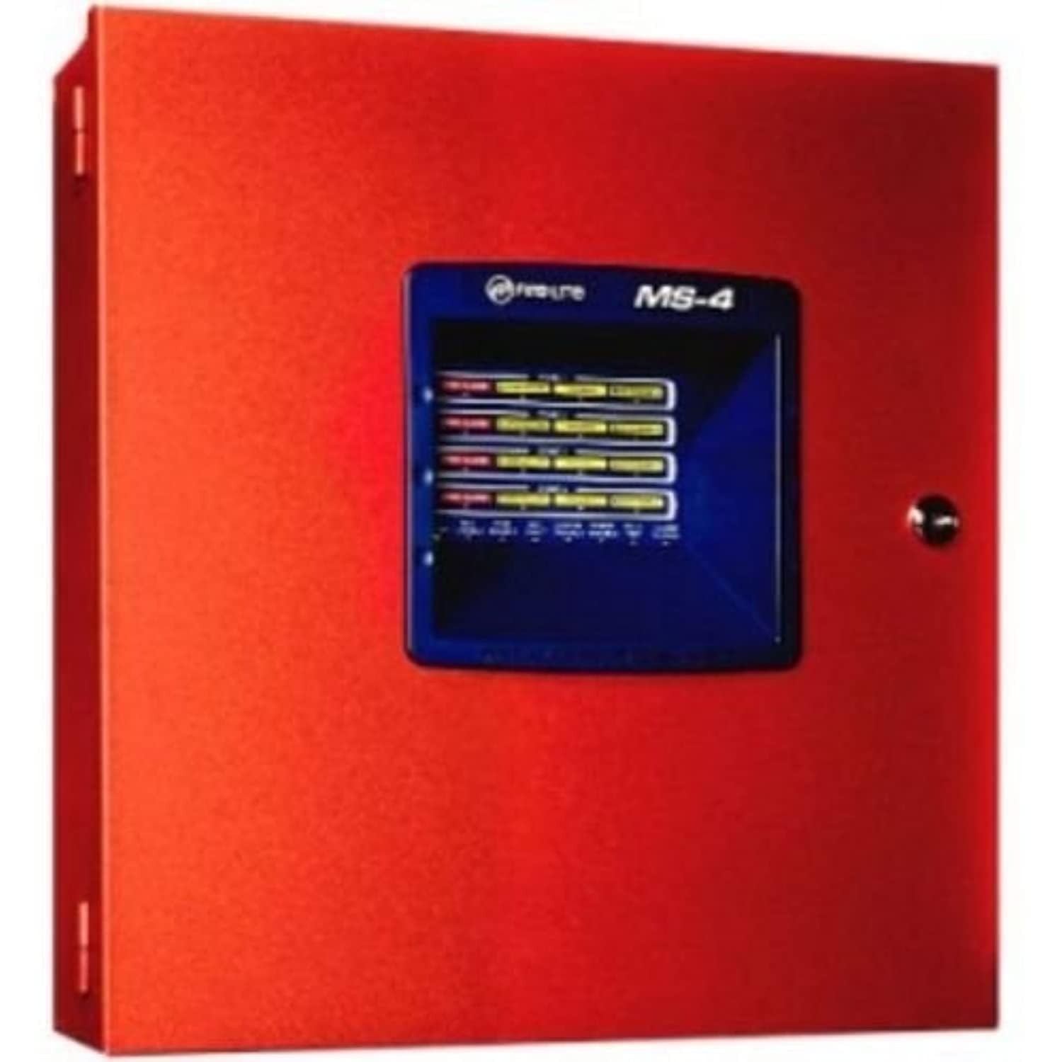
Figure 1: Front view of the Fire-Lite Alarms MS-4 Fire Alarm Control Panel. The panel is red with a central display showing zone indicators and control buttons. A key is inserted into a lock on the right side of the display.
2. Key Features
- Four Conventional Zones: Each zone supports a variety of initiating devices such as smoke detectors and manual pull stations.
- Two Class B Notification Appliance Circuits (NACs): Provides power and control for audible and visual notification devices.
- Front Panel Controls: Easy access buttons for Acknowledge (ACK), Alarm Silence, Reset, and Walk Test.
- LED Indicators: Clear LED status indicators for Fire Alarm, Supervisory, Trouble, and Maintenance for each zone, as well as system status.
- Compact Design: Designed to fit comfortably in utility rooms or hallways.
- Simple Wiring: Clearly labeled connections for easy installation and maintenance.
- 120 VAC Operation: Standard power input for typical installations.
3. Setup and Installation
Installation of the MS-4 panel should only be performed by qualified personnel in accordance with all national and local electrical codes and standards. Ensure all power is disconnected before beginning installation.
3.1 Mounting the Panel
The MS-4 panel is designed for surface mounting. Choose a location that is dry, free from excessive vibration, and easily accessible for operation and maintenance. Ensure adequate clearance around the panel for ventilation and wiring access.
3.2 Wiring Connections
The internal components of the MS-4 panel feature clearly labeled terminals for all connections. Refer to the wiring diagrams provided in the full installation manual for detailed instructions. Key connections include:
- AC Power: Connect 120 VAC, 50/60 Hz power to the designated terminals.
- Initiating Device Circuits (IDCs): Connect smoke detectors, heat detectors, and manual pull stations to the four zone terminals (Zone 1-4). Ensure proper end-of-line resistor placement as specified.
- Notification Appliance Circuits (NACs): Connect horns, strobes, and other notification devices to the NAC terminals. Observe polarity and ensure proper end-of-line resistor placement.
- Auxiliary Outputs: If applicable, connect auxiliary devices to the auxiliary output terminals.
- Grounding: Ensure the panel is properly grounded according to local codes.
After all wiring is complete, secure the panel door and ensure the key is accessible for authorized personnel.
4. Operating Instructions
The MS-4 panel features intuitive front-panel controls for managing system status and responding to events.
4.1 Control Buttons
- ACK (Acknowledge): Press this button to acknowledge new alarms, supervisory signals, or trouble conditions. This silences the panel's internal buzzer.
- ALARM SILENCE: Press this button to silence activated notification appliances (horns, strobes). The alarm condition will remain indicated on the panel until reset.
- RESET: After an alarm condition has been cleared and notification appliances silenced, press this button to reset the system. This will restore initiating devices to their normal operating state.
- WALK TEST: Used to initiate a system walk test. Refer to the full manual for detailed walk test procedures.
- ZONE ENABLE/DISABLE (Buttons 1-4): These buttons, typically requiring a key or specific access level, allow for enabling or disabling individual zones for maintenance or testing purposes.
4.2 Responding to Alarms
- Upon a fire alarm, the panel's internal buzzer will sound, and the "FIRE ALARM" LED for the affected zone(s) will illuminate. Notification appliances will activate.
- Press the ACK button to acknowledge the alarm and silence the panel's internal buzzer.
- Investigate the cause of the alarm. Ensure the area is safe before proceeding.
- Once the alarm condition is confirmed to be clear, press the ALARM SILENCE button to silence the notification appliances.
- Press the RESET button to restore the system to normal operation. If the alarm condition persists, the system will re-alarm.
5. LED Indicators
The MS-4 panel provides clear visual feedback through its front-panel LED indicators. These LEDs help identify the status of each zone and the overall system.
| Indicator | Description |
|---|---|
| AC POWER (Green) | Illuminates steadily when primary AC power is present. Flashes if AC power is lost and the system is running on battery backup. |
| FIRE ALARM (Red) | Illuminates steadily for an active fire alarm in the corresponding zone. |
| SUPERVISORY (Yellow) | Illuminates steadily for a supervisory condition in the corresponding zone. |
| TROUBLE (Yellow) | Illuminates steadily for a trouble condition (e.g., open circuit, short circuit) in the corresponding zone or system. |
| MAINTENANCE (Yellow) | Indicates a maintenance required condition for the corresponding zone. |
| NAC DISABLE (Yellow) | Illuminates when Notification Appliance Circuits are disabled. |
| SYSTEM TROUBLE (Yellow) | Indicates a general system trouble condition. |
| POWER TROUBLE (Yellow) | Indicates a trouble condition related to the power supply or battery. |
| ALARM SILENCE (Yellow) | Illuminates when notification appliances have been silenced. |
6. Maintenance
Regular maintenance is crucial for ensuring the continued reliable operation of your Fire-Lite Alarms MS-4 panel and connected devices. All maintenance should be performed by qualified personnel.
6.1 Daily Checks
- Verify the AC POWER (green) LED is steadily illuminated.
- Check for any illuminated yellow TROUBLE or MAINTENANCE LEDs. If any are lit, investigate and resolve the issue.
6.2 Weekly/Monthly Checks
- Perform a Walk Test to ensure all initiating devices and notification appliances are functioning correctly.
- Test the battery backup system by temporarily disconnecting AC power and verifying the panel operates on batteries. Reconnect AC power after the test.
6.3 Annual Professional Inspection
It is highly recommended to have a certified fire alarm technician inspect and test the entire system annually, or more frequently as required by local codes. This includes testing all detectors, pull stations, notification appliances, and verifying battery health and system programming.
7. Troubleshooting
This section provides basic troubleshooting steps for common issues. For complex problems, contact a qualified fire alarm technician.
7.1 Trouble LED Illuminated
- No AC Power (AC POWER LED off or flashing): Check the circuit breaker for the panel's power supply. Ensure the power cord is securely plugged in.
- Zone Trouble LED: This often indicates an open circuit (broken wire) or a short circuit in the initiating device circuit. Inspect wiring for damage, loose connections, or incorrect end-of-line resistors.
- NAC Trouble LED: Similar to zone trouble, this can indicate an issue with the notification appliance circuit wiring or a faulty device.
- Battery Trouble: The system batteries may be low, discharged, or faulty. Check battery connections and voltage. Batteries typically need replacement every 3-5 years.
7.2 False Alarms
- Smoke Detector Activation: Check for sources of smoke, dust, steam, or insects near the detector. Clean detectors regularly.
- Manual Pull Station: Ensure the pull station was not accidentally activated.
- Environmental Factors: Rapid temperature changes or high humidity can sometimes trigger detectors.
Always address trouble conditions promptly to ensure the fire alarm system is fully operational.
8. Specifications
| Attribute | Detail |
|---|---|
| Brand | Fire Lite Alarms |
| Model Number | MS-4 |
| Description | Four-zone conventional fire alarm control panel |
| Power Source | Corded Electric (120 VAC, 50/60 Hz, 2.3 A) |
| Number of Zones | 4 |
| NACs | 2 Class B |
| Alarm Type | Audible |
| Color | Red |
| Item Weight | 8 ounces (0.5 Pounds) |
| Package Dimensions | 16.2 x 16 x 4.2 inches |
| Batteries Required? | No (for primary operation, but typically requires backup batteries, sold separately) |
9. Safety Information
- Electrical Hazard: Installation and servicing must be performed by qualified personnel only. Disconnect all power before working on the panel.
- Battery Safety: If using backup batteries, ensure they are correctly installed and maintained. Refer to battery manufacturer guidelines for safe handling and disposal.
- System Integrity: Never disable or bypass any part of the fire alarm system unless for authorized testing or maintenance.
- Regular Testing: Test the system regularly as per local codes and manufacturer recommendations to ensure proper operation.
- Emergency Procedures: Familiarize all occupants with the sound of the fire alarm and the appropriate emergency evacuation procedures.
10. Warranty and Support
For specific warranty information, please refer to the documentation included with your Fire-Lite Alarms MS-4 panel or contact Fire-Lite Alarms directly. Keep your purchase receipt as proof of purchase.
For technical support, installation assistance, or service, please contact your authorized Fire-Lite Alarms dealer or a certified fire alarm technician. Do not attempt to repair the panel yourself, as this may void the warranty and compromise system safety.
You can find additional resources and contact information on the official Fire-Lite Alarms website.