Introduction
The Go Power! GP-SW1500-12 is a 1500-watt pure sine wave inverter designed to convert 12V DC battery power into 120V AC household electricity. This inverter provides clean, stable power suitable for sensitive electronics, making it ideal for various applications including RVs, marine, and off-grid systems. This manual provides essential information for the safe and efficient operation of your inverter.
Important Safety Information
Please read and understand all safety instructions before installing or operating the inverter. Failure to follow these instructions may result in electrical shock, fire, serious injury, or property damage.
- Electrical Shock Hazard: Do not open the inverter casing. There are no user-serviceable parts inside. Refer servicing to qualified personnel.
- Fire Hazard: Do not install the inverter in areas where flammable materials or gases are present. Ensure adequate ventilation to prevent overheating.
- Battery Safety: Always connect the inverter to a 12V DC battery system. Ensure correct polarity (positive to positive, negative to negative). Reverse polarity will damage the unit.
- Wiring: Use appropriate gauge wiring for DC input connections as specified in the installation section. Improper wiring can lead to overheating and fire.
- Grounding: The inverter must be properly grounded to a chassis ground lug.
- Ventilation: Ensure the inverter's ventilation ports are clear and unobstructed to allow for proper cooling.
Product Features and Components
Front Panel Overview
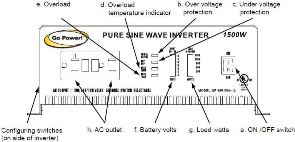
This image displays the front panel of the Go Power! GP-SW1500-12 Pure Sine Wave Inverter. Key components include:
- a. ON/OFF Switch: Main power switch for the inverter.
- b. Over Voltage Protection Indicator: LED illuminates if input voltage exceeds safe limits.
- c. Under Voltage Protection Indicator: LED illuminates if input voltage drops below safe limits.
- d. Overload Temperature Indicator: LED illuminates if the inverter overheats.
- e. Overload Indicator: LED illuminates if the connected load exceeds the inverter's capacity.
- f. Battery Volts Display: LED bar graph indicating the current DC input voltage (10-14V).
- g. Load Watts Display: LED bar graph indicating the current AC output wattage (0-1500W).
- h. AC Outlets: Standard 120V AC outlets for connecting appliances.
- Configuring Switches (on side of inverter): Switches for selecting 100/120V and 50/60Hz output.
Rear Panel Overview

This image shows the rear panel of the Go Power! GP-SW1500-12 Pure Sine Wave Inverter. Key components include:
- a. Ventilation Ports: Fans and grilles for cooling the inverter.
- b. Battery Terminals (DC Input): Heavy-duty terminals for connecting 12V DC battery cables. Marked "NEG -" and "POS +".
- c. RS-232C Jack: Serial communication port (for advanced monitoring/control, not typically user-configurable).
- d. Chassis Ground Lug: Terminal for connecting the inverter to a vehicle chassis or earth ground.
Setup and Installation
Proper installation is critical for the safe and efficient operation of your inverter. Consult a qualified electrician if you are unsure about any steps.
- Mounting Location: Choose a dry, cool, and well-ventilated area. Avoid direct sunlight, heat sources, and areas with excessive dust or moisture. Ensure sufficient clearance around the ventilation ports.
- DC Input Wiring:
- Use heavy-gauge cables (e.g., 2 AWG or larger for typical installations) to connect the inverter to your 12V battery bank. The cable length should be as short as possible to minimize voltage drop.
- Install an appropriate DC fuse or circuit breaker (e.g., 200A for a 1500W inverter) as close to the battery positive terminal as possible.
- Connect the positive (+) cable from the battery to the positive (+) terminal on the inverter.
- Connect the negative (-) cable from the battery to the negative (-) terminal on the inverter.
- Ensure all connections are tight and secure. Reverse polarity will cause immediate damage to the inverter.
- Chassis Grounding: Connect the chassis ground lug on the inverter to a reliable earth ground or vehicle chassis using a suitable wire.
- AC Output Configuration: Use the configuring switches on the side of the inverter to select the desired AC output voltage (100V or 120V) and frequency (50Hz or 60Hz). Ensure these settings match the requirements of your appliances.
Operating Instructions
- Power On: Ensure all DC connections are secure and the inverter is properly grounded. Flip the ON/OFF switch (a) to the "ON" position. The inverter will perform a self-test, and the battery volts display (f) should illuminate.
- Connecting Appliances: Plug your 120V AC appliances into the AC outlets (h) on the front panel.
- Monitoring: Observe the Load Watts display (g) to monitor the power consumption of your connected devices. The Battery Volts display (f) indicates the current battery voltage.
- Power Saving Mode: The GP-SW1500-12 features a power-saving mode. If the inverter detects a very low load (typically below 8-40 watts), it may enter a standby state to conserve battery power. In this mode, the AC output may appear to be off or at a very low voltage. To activate the AC output for low-wattage devices, you may need to connect a higher-wattage device first, or cycle the inverter's power switch.
- Power Off: Before disconnecting any appliances, flip the ON/OFF switch (a) to the "OFF" position.
Maintenance
The Go Power! GP-SW1500-12 inverter requires minimal maintenance.
- Cleaning: Periodically clean the exterior of the inverter with a dry cloth. Ensure the ventilation ports are free from dust and debris. Do not use liquid cleaners.
- Connections: Regularly check all DC input and ground connections to ensure they are tight and free from corrosion. Loose connections can cause overheating and poor performance.
- Battery Health: Maintain your battery bank according to the manufacturer's recommendations to ensure optimal inverter performance and longevity.
Troubleshooting
This section addresses common issues you might encounter with your inverter.
| Problem | Possible Cause | Solution |
|---|---|---|
| No AC output, inverter off. | Inverter switch is OFF. Low battery voltage. Blown DC fuse/breaker. Loose DC connections. | Turn ON the inverter switch. Recharge or replace battery. Check and replace fuse/reset breaker. Tighten all DC connections. |
| Overload indicator (e) is ON. | Connected load exceeds 1500W continuous or 2000W peak. | Reduce the total wattage of connected appliances. Turn inverter OFF, then ON again. |
| Overload Temperature indicator (d) is ON. | Inverter is overheating. Blocked ventilation. Excessive ambient temperature. | Allow inverter to cool down. Clear any obstructions from ventilation ports. Move inverter to a cooler location. |
| Under Voltage Protection indicator (c) is ON. | Battery voltage is too low (below 10.5V alarm, 10.0V shutdown). | Recharge the battery. Disconnect loads to prevent deep discharge. |
| Over Voltage Protection indicator (b) is ON. | Input voltage is too high (above 16.0V). | Check the charging system or battery source. Ensure input voltage is within 11.0-16.0VDC. |
| Low wattage device does not power on. | Inverter is in Power Saving Mode. | Connect a higher wattage device to activate the AC output, or cycle the inverter's power switch OFF then ON. |
Specifications
- Model: GP-SW1500-12
- Continuous Output Power: 1500 Watts
- Peak Output Power: 2000 Watts (Note: Some descriptions may incorrectly state 3000 Watts peak. Refer to the manual for accurate specifications.)
- DC Input Voltage: 12V DC (Operating range 11.0-16.0VDC)
- AC Output Voltage: 100V / 120V (Selectable)
- AC Output Frequency: 50Hz / 60Hz (Selectable)
- Output Waveform: Pure Sine Wave
- Low Voltage Alarm: 10.5V
- Low Voltage Shutdown: 10.0V
- Product Dimensions: 18.75 x 13.75 x 7.25 inches
- Item Weight: 17 pounds
- Manufacturer: Go Power!
Warranty and Support
Go Power! typically offers a warranty for their products. It is important to review the specific warranty terms provided with your purchase, as they may vary.
- Warranty Period: Refer to your product documentation for the exact warranty duration. Some user experiences indicate that after two years, units may be considered non-serviceable by the manufacturer.
- Coverage: Warranties generally cover defects in materials and workmanship under normal use. They typically do not cover failures due to improper installation, misuse, or "normal wear and tear."
- Non-Transferable: Warranties are often non-transferable and apply only to the original purchaser.
- Customer Support: For technical assistance, warranty claims, or service inquiries, please contact Go Power! customer support directly. Contact information can usually be found on the manufacturer's website or in the product packaging.
Note: Always retain your proof of purchase for warranty purposes.