1. Introduction
The Eltako ES12Z-200 is a modular impulse relay designed for inline installation on a DIN-EN 50 022 rail. This device features galvanically isolated working contacts and centralized control inputs, allowing for local control with a different phase and voltage than the centralized system. It includes a rotary switch for setting different priorities between control inputs and determining the device's behavior (switch off or maintain position) after a power failure.
This manual provides essential information for the safe and efficient installation, operation, and maintenance of your Eltako ES12Z-200 impulse relay.
2. Key Features
- Modular design for DIN rail mounting (1 module unit = 18mm wide).
- Wide control voltage range: 8 to 230 V AC/DC.
- Galvanically isolated control inputs for flexible local and centralized control.
- Integrated rotary switch for priority selection and power failure behavior.
- Two normally open (NO) contacts.
- Rated current: 16 A.
3. Technical Specifications
| Specification | Value |
|---|---|
| Manufacturer | Eltako |
| Model Number | ES12Z-200 (21200601) |
| Mounting Type | DIN Rail |
| Width in Module Units | 1 (18 mm) |
| Number of Normally Open Contacts (NO) | 2 |
| Control Voltage Range | 8 to 230 V AC/DC |
| Rated Current | 16 A |
| Operating Mode | ON-OFF |
| Product Dimensions (L x W x H) | 9.5 x 6 x 2.5 cm |
| Weight | 70 grams |
| Material | Neon (for indicator lamp) |
| Spare Parts Availability | Information not available |
4. Safety Information
WARNING: Electrical shock hazard. Installation and maintenance should only be performed by qualified electricians in accordance with all national and local electrical codes and regulations.
- Always disconnect power before installing, servicing, or removing the device.
- Ensure proper grounding and wiring connections.
- Do not exceed the specified voltage and current ratings.
- Protect the device from moisture, dust, and extreme temperatures.
- Verify all connections are secure before restoring power.
5. Installation
5.1 Mounting
The Eltako ES12Z-200 is designed for mounting on a standard DIN-EN 50 022 rail. Ensure sufficient space for ventilation and access to terminals.
5.2 Wiring Diagram
Refer to the wiring diagram below for correct electrical connections. The device supports both local and centralized control inputs with galvanic isolation.

Image 1: Wiring diagram for the Eltako ES12Z-200 impulse relay. This diagram illustrates the connections for the main power supply (L, N), local control input, centralized control inputs (central on, central off), and the output contacts (1, 2). It also shows the internal circuitry for the control voltage and the 16A/250V output rating.
5.3 Connection Steps
- Power Supply: Connect the live (L) and neutral (N) wires to the designated terminals as shown in the diagram. The device operates with a supply voltage range of 8-230V AC/DC.
- Local Control: Connect your local push-button or switch to the 'local on/off' input. This input typically requires a control current of up to 150mA for neon lamps from 110V.
- Centralized Control: Connect centralized 'on' and 'off' control signals to the respective terminals. These inputs are galvanically isolated, allowing for different control voltages or phases.
- Output Contacts: Connect the load (e.g., lighting circuit) to the output contacts (1 and 2). The relay provides two normally open (NO) contacts with a maximum current rating of 16A at 250V.
- Verification: Double-check all connections for correctness and security before applying power.
6. Operation
6.1 Basic Functionality
The Eltako ES12Z-200 functions as an impulse relay. A brief pulse to any activated control input (local, central on) will toggle the state of the output contacts. A pulse to the central off input will switch the contacts to the OFF state.
6.2 Priority Selection and Power Failure Behavior
The device features a rotary switch on its front panel to configure priority settings for control inputs and define behavior during power failures.
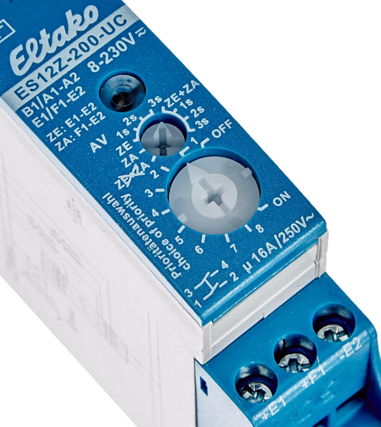
Image 2: Close-up view of the Eltako ES12Z-200 rotary switch. This switch allows users to select different priority levels for control inputs and configure the relay's response to power outages, such as switching off or maintaining its current state.
The rotary switch allows you to:
- Set different priority levels for the various control inputs (e.g., local vs. centralized).
- Determine the relay's state after a power failure: either switch off or maintain its last switching position upon power return. Consult the specific markings on your device for detailed settings.
7. Maintenance
The Eltako ES12Z-200 impulse relay is designed for long-term, maintenance-free operation under normal conditions. However, periodic checks are recommended:
- Visual Inspection: Periodically inspect the device for any signs of physical damage, overheating, or loose connections.
- Cleaning: If necessary, gently clean the exterior of the device with a dry, soft cloth. Do not use liquid cleaners or solvents.
- Terminal Tightness: Ensure all terminal screws remain tight to prevent poor contact and potential overheating.
Always disconnect power before performing any inspection or cleaning.
8. Troubleshooting
If you encounter issues with your Eltako ES12Z-200, refer to the following table for common problems and solutions:
| Problem | Possible Cause | Solution |
|---|---|---|
| Relay does not respond to control input. | No power supply; incorrect wiring; faulty control switch; control voltage outside range. | Check power supply to L and N terminals. Verify all wiring connections against the diagram. Test the control switch. Ensure control voltage is within 8-230V AC/DC. |
| Load does not switch ON/OFF. | Faulty load; incorrect load wiring; overloaded contacts. | Check the load (e.g., light bulb). Verify wiring to output contacts. Ensure load current does not exceed 16A. |
| Relay switches erratically. | Interference; loose connections; faulty device. | Check for sources of electrical interference. Tighten all terminal connections. If problem persists, the device may be faulty and require replacement. |
| Device gets excessively hot. | Overloaded contacts; poor ventilation; loose connections. | Reduce load if exceeding 16A. Ensure adequate ventilation around the device. Tighten all connections. |
9. Warranty and Support
Information regarding a manufacturer's warranty for the Eltako ES12Z-200 is not explicitly provided. This product may be subject to the terms of a private sale without warranty, as indicated in some product descriptions. Additionally, information on the availability of spare parts is not available.
For any warranty claims or technical support, please contact your point of purchase or the seller directly. They can provide details on applicable return policies or support options.
10. Product Dimensions
The Eltako ES12Z-200 is a compact device, designed to fit within standard electrical enclosures.

Image 3: The Eltako ES12Z-200 impulse relay shown in hand, providing a visual reference for its compact dimensions. The image highlights a height of approximately 2.6 inches (6 cm).


